FREE 1 to 3-Day Delivery on Orders $149+ Details
How to Install Corsa 3 in. Sport Cat-Back Exhaust w/ Polished Tip - Single Side Exit (03-07 5.7L RAM 1500) on your Dodge RAM
Tools Required
- Safety Glasses
- 15mm Wrench or Deep Socket
- 3/8" Ratchet
- Grommet Pullers
- 12" Ratchet Extension
- Torque Wrench
- Soap &Water Solution
- 9/16" Socket

Shop Parts in this Guide
Please take time to reac and understanc these installation instructions.
We recommend that the installation of this system be performed by a qualified service center or professional muffler installer who has the necessary equipment, tools and experienced personnel. However, if you decide to perform this install, the use of a hoist and an additional person will be required.
CAUTION: Never work on a hot exhaust system. Allow time for the vehicle to cool. Always wear eye protection when working under a vehicle.
NOTE: The supplied double edge clamps in this system will crush and permanently deform the exhaust piping as they are tightened. DO NOT tighten these clamps any more than is necessary to lightly hold the exhaust components in place, until the very end of this installation process. It will be difficult or impossible to make any positional or rotational adjustments to the exhaust system after these clamps have been tightened down.
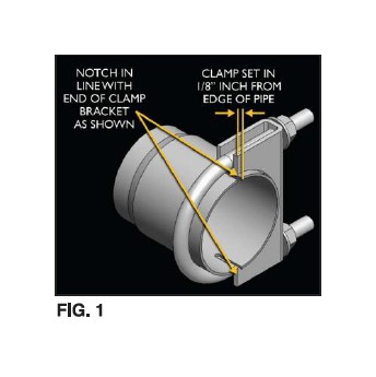
VERY IMPORTANT: Align all clamps so that the open edge of the clamp bracket is parallel and aligned with the notch in the pipe, and the outside edge of the clamp bracket is approximately 1/8" from the end of the pipe expansion. (See Fig. 1) Failure to properly position or orient the clamps could result in a weak ciampinc load, or even a potential leak at the clamp joints.
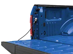
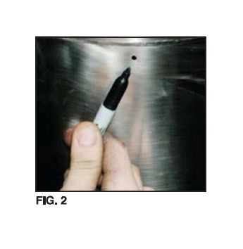
IMPORTANT: Make sure that the small drain holes in the muffler are facing down when the muffler is installed. (See Fig. 2)
Stock Exhaust Removal Instructions
FOR 2003 REGULAR CAB / SHORT BED & 2003-05 QUAD CAB MODELS:
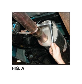
1) Unbolt intermediate-to-header pipe clamp using a 15mm socket (See Fig. A) Be sure to support muffler to prevent injury. Use lubricant to loosen clamp bolt if necessary. Continue to page 5 and follow instructions beginning with 2.
FOR 2004 REGULAR CAB / SHORT BED MODELS:
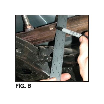
1) First you need to place a reference mark on the front Y-Pipe on the Passenger side. LocatE the cross member and usinc a ruler hold it vertically against the cross member and the torsion bar (See Fig B). Now mark the Y-Pipe.
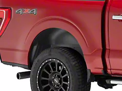
FOR 4WD MODELS:
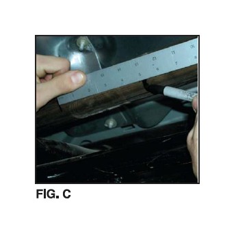
1A) Measure 5-inches from the Y-Pipe mark towards the Muffler and mark the Y-Pipe. This will be where you will cut the Y-Pipe (See Fig C).
OR
FOR 2WD MODELS:
1A) Measure ONLY 2-inches from the Y-Pipe mark towards the Muffler and mark the Y-Pipe. This will be where you will cut the Y-Pipe.
1B) Check measurements again.
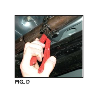
1C) Use a chain-style pipe cutter to makE your (See Fig D).
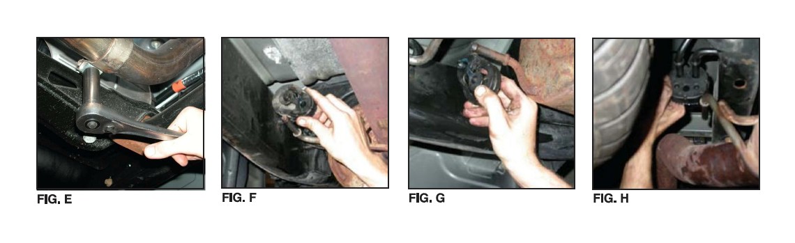
1) Next remove the clamp from the Y-Pipe on the Driver Side using a 15mm socket. Note that there is a spot weld along side of the clamp where it meets the jointing of the Y-Pipe and Header pipe. THIS SPOT WELD MUST BE BROKEN. It is suggested that a grinding wheel be used to break the spot weld (See Fig E).
2) Next, remove the two (2) rubber insulators from the hangers, located just in front of the muffler (near muffler inlet) (See Fig. F & G). It may be easier to first remove rubber insulator from frame hanger. Be sure to keep the rubber insulator.
NOTE: The use of soapy water solution may aid in the remove I and later installation of the hangers in the rubber isolators.
3) Remove two (2) rubber insulators from hangers at the rear of Muffler and the Tail Pipe insulator (See Fig. H). Be sure to KEEP insulators as they will be required for the installing of your new exhaust system. 4) The factory system can now be removed in one piece.
dB Performance Exhaust Installation Instructions
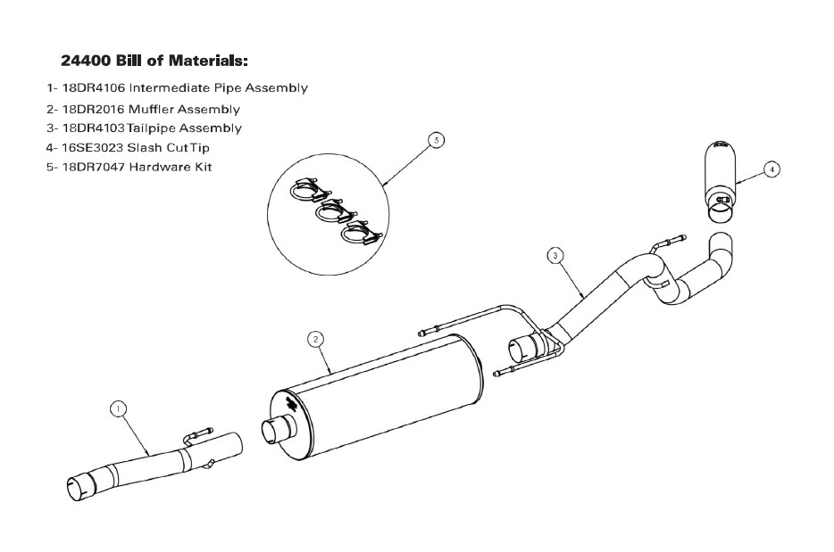
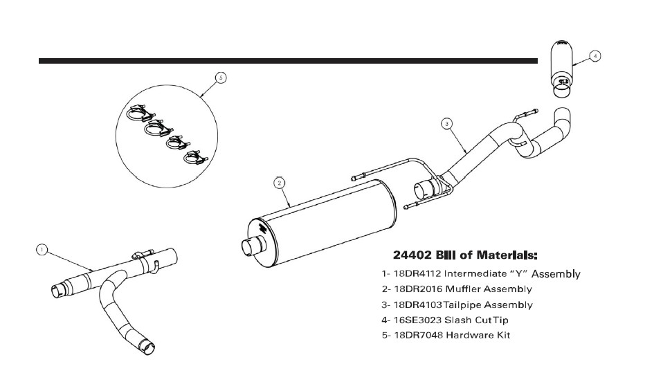
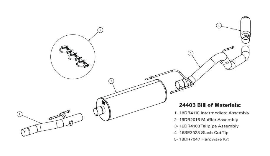
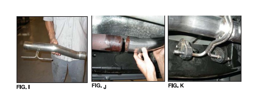
5) FOR 2003 REGULAR CAB / SHORT BED & 2003-04 QUAD CAB MODELS: Locate intermediate Pipe (See Fig. I) and slide expanded end over header pipe (See Fig. J). Position clamp and hand tighten only. Insert Intermediate Pipe hangers into rubber insulators (See Fig. K).
OR
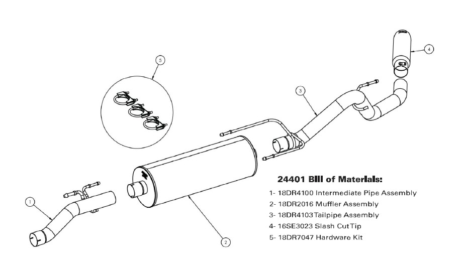
5) FOR 2004 REGULAR CAB / SHORT BED MODELS:
Locate front Y-Pipe and position Passenger Side into Header Pipe and repeat for Driver Side. Snug fit clamps at this time.
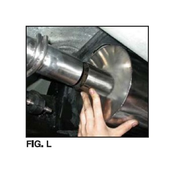
6) Next, slide slotted end of muffler onto Intermediate or Y-Pipe and slide a clamp over Muffler Inlet Pipe (See Fig. L) Snug fit the clamp. Do not tighten clamp at this time.
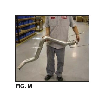
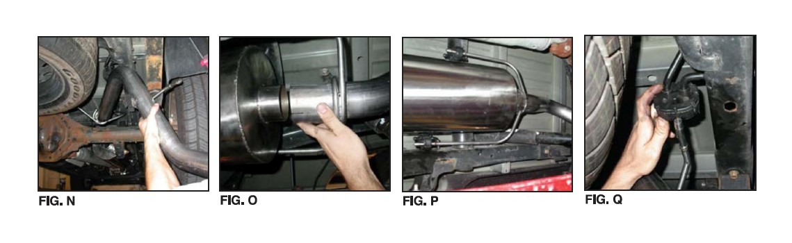
7) Locate Tail Pipe (See Fig. M) and position "fork" end of Tail Pipe (with two hangers) over axle housing (See Fig. N). Next, slide over Muffler outlet and place a clamp over Tail Pipe inlet (See Fig. 0). Snug fit clamp.
8) Insert Tail Pipe hangers into rubber insulators (See Fig. P & Q). NOTE: It may bE easier to insert hanger into rubber insulator before sliding pipe over Muffler outlet.
8) Insert Tail Pipe hangers into rubber insulators (See Fig. P & Q). NOTE: It may bE easier to insert hanger into rubber insulator before sliding pipe over Muffler outlet. 9) Locate dB slash cut tip . Slide over Tailpipe Extension. Snuc -fit the clamp. Do not tighten clamp at this time.
10) Check alignment of tip and be sure to allow a one-inch gap between the top of the Tip Assembly and the body panel. Make necessary adjustments, including fore and aft, and tighten clamp.
11) Starting with the Intermediate-to-Header and working back, tighten all clamps as described in Figure 1 on the first page. TorquE all suppliec clamps to 35 ft-Ibs; Tip clamp to 16-20 ft.-lbs.
12) It is STRONGLY SUGGESTED that all clamps be checked and re-tic htened (if necessary) to the recommended torquE after initial road testinc of the vehicle, as thermal cycling has occurred on the system. Please wait until system has fully cooled to conduct this process.
NOTE: During cold weather start-ups, you may experience an exhaust sound that is deeper and louder in tone than usual. This is temporary and will diminish to normal levels once your engine has reached Its normal operating temperature.
NOTE: Immediately following the Installation of your exhaust system, you may experience a trace of smoke after initial start-up. DO NOT be alarmed. The smoke is caused by the burning of a small amount of forming oil residue used in the manufacturing process.