 FREE 1 to 3-Day Delivery on Orders $149+ Details
How to Install Auto Meter Factory Match Boost Gauge - 0-100PSI - Mechanical (09-17 RAM 1500) on your Dodge RAM

Shop Parts in this Guide
ON MECHANICAL VAC/BOOST GAUGES
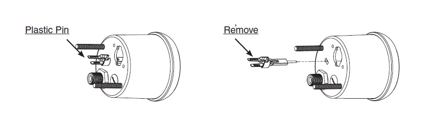
To maintain proper calibration during shipping, the pointer of this gauge is held off zero by a plastic “pin” inserted into the gauge case and movement. This pin MUST BE REMOVED and discarded prior to installation and operation
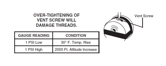
VENTING FOR LIQUID FILLED GAUGES ONLY
Auto Meter’s Pro Comp Liquid Filled Gauges are equipped with a vent screw on the top of the case. Internal case pressure can change due to altitude, barometric pressure, and temperature, causing an inaccurate or “off zero” reading on more sensitive low pressure gauges such as 0-15 psi fuel pressure, vacuum, boost, and vacuum/boost gauges. To prevent this it is recommended that the gauge be vented. With the vent screw in the upright position, turn the screw two turns counterclockwise to equalize the gauge case pressure. This allows the gauge to breathe and self adjust.
Note on Ultra-Nite (Glow In The Dark)
The glow in the dark coating on the dial of the Ultra-nite gauge may turn gray if exposed to direct sunlight for extended periods of time. When the car is not being used and will be in direct sunlight for long periods of time, place the provided red plastic cover on the gauge.
LED REPLACEMENT KITS ARE SOLD ONE PER PACKAGE
3284-Red LED Replacement Kit, 3285-Green LED Replacement Kit, 3286-Blue LED Replacement Kit, 3287-Amber LED Replacement Kit, 3288-White LED Replacement Kit
Metric Adapters
If this product is to be installed on a vehicle requiring metric fittings, please contact your local Auto Meter dealer to purchase metric adapters. A complete listing of the fittings available can be found in our catalog or online at http://www.autometer.com
PRESSURE, VACUUM & BOOST GAUGES
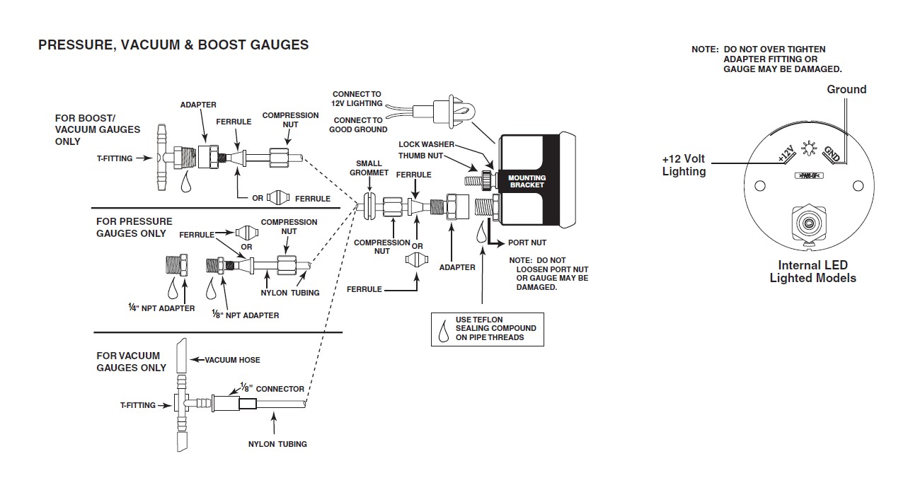
NOTE: Some late model vehicles use electronic sensors in their pressure and temperature senders for engine control functions. Before removing the original sender, we recommend that you contact your automotive dealer to be sure no critical functions will be disrupted. With pressure gauges, it is beneficial to add a T-fitting to install your new gauge and to keep the warning light operational. This allows you to monitor the pressure and still have a warning light to indicate emergency conditions.
1. Gauges may be mounted in In-dash holes, or in Auto Meter custom mounting Solutions. Secure gauge with mounting clamps supplied. 2-1⁄16”gauges mount in 2-1⁄16” diameter hole, 2-5⁄8” gauges mount in 2-5⁄8” diameter hole.
2. Drill 3⁄8” dia. holes and install rubber grommet where pressure or vacuum line passes through sheet metal, such as firewall.
3. Attach nylon pressure line to fitting on back of gauge using adapter, ferrule, and compression nut as shown in diagram above. Route line through grommet to engine compartment. Connect line to pressure port on engine by using 1⁄8” adapter (1⁄4” if needed), ferrule and compression nut for pressure gauges or 1⁄8” connector and T-fitting for vacuum gauges.
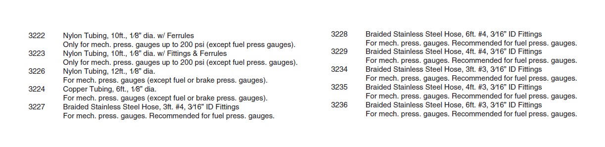
4. Make sure line is free from hazard of moving parts or hot engine components. It is recommended that Auto Meter 3224 copper tubing kit be used where a potential hazard exits.
5. Start engine and thoroughly check installation for leaks.
6. Twist in light socket assembly and connect one wire to dash lighting circuit or other 12V power source and the other wire to a good ground.
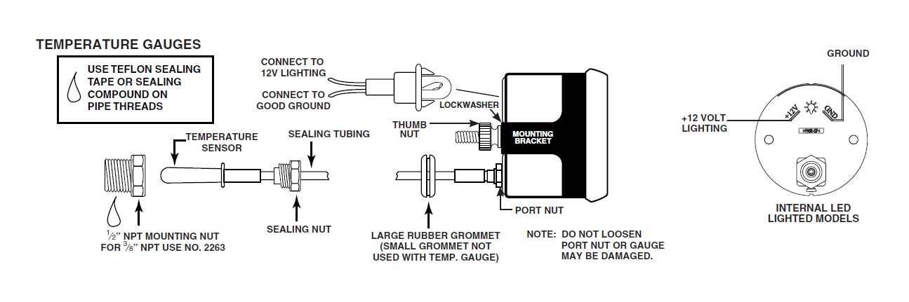
NOTE: Some late model vehicles use electronic sensors in their pressure and temperature senders for engine control functions. Before removing the original sender, we recommend that you contact your automotive dealer to be sure no critical functions will be disrupted.
1. Gauge may be mounted in-dash or in the Auto Meter custom mounting solutions. Secure gauge with mounting clamps supplied. 2-1⁄16" gauges mount in 2-1⁄16" diameter hole, 2-5⁄8" gauges mount in 2-5⁄8" diameter hole.
CAUTION: DO NOT make severe bends in the capillary tubing. It may break internally, thus, voiding the warranty. DO NOT remove capillary tubing from gauge.
2. Cut a 7⁄8" dia. hole in firewall. Place grommet on capillary tubing. A slit must be made in the grommet to accomplish this. Route sensing bulb through firewall and secure grommet in the 7⁄8" hole.
3. Insert and tighten mounting nut in the 1⁄2" NPT port on engine. (For engines with a 3⁄8" NPT port use Auto Meter adapter # 2263). Insert temperature sensing bulb in the mounting nut and carefully tighten sealing nut, while holding mounting nut. The Oil Temperature gauge usually requires drilling a hole and welding the Auto Meter # 2261 steel weld fitting in the oil pan. Be sure to check for adequate internal clearances for the temperature sensing bulb. Install temperature sensing bulb as described above.
4. Make sure gauge tubing is free from hazard of moving parts or hot engine components.
5. Start engine and thoroughly inspect installation for any leaks.
6. Twist in light socket assembly and connect one wire to dash lighting circuit or other 12V power source and the other wire to a good ground.
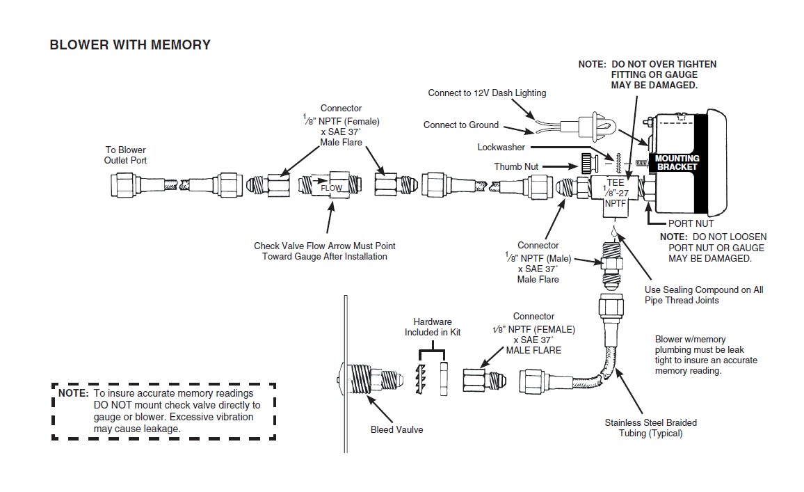
1. Secure two 1⁄8"-27 NPTF x #4 SAE 37˚ flare connectors to the 1⁄8"-27 NPTF tee as shown in the installation above. NOTE: The connector flare (37˚) must be compatible with the ends on the stainless steel braided tubing. Auto Meter braided stainless steel tubing no. 3227 and 3228 include #4 SAE 37˚ flare female swivel ends.
2. Drill 3⁄8" dia. hole and install rubber grommet where pressure line passes through firewall into engine compartment.
3. Secure two 1⁄8"-27 NPT female x SAE 37˚ male flare connectors to the check valve as shown above. Secure the check valve and connector assembly to one end of a length of braided stainless steel tubing. NOTE: The arrow on the check valve must be pointing toward the gauge as shown in the diagram above.
4. Secure the opposite end of the tubing and check valve assembly to the tee on the back of the gauge. Route the pressure line through the firewall into the engine compartment. Connect another length of braided stainless steel tubing between the check valve and the blower outlet port. NOTE: Keep line clear of moving parts or hot engine components.
5. Secure a 1⁄8"-27 NPTF female x SAE male flare connector to the bleed valve.
6. Using the nut and lock washer provided, secure the bleed valve and connector assembly in-dash or wherever it is convenient for the driver.
7. Connect length of braided stainless steel tubing between the tee on back of gauge and the bleed valve.
8. Start engine and thoroughly check for any leaks. When engine is shut off, gauge should not leak down until bleed valve is pushed. If gauge leaks, check and tighten all connections.
9. Connect the WHITE light wire to dash lighting circuit or other 12V source. Connect the BLACK light wire to a good engine ground. (which applicable)
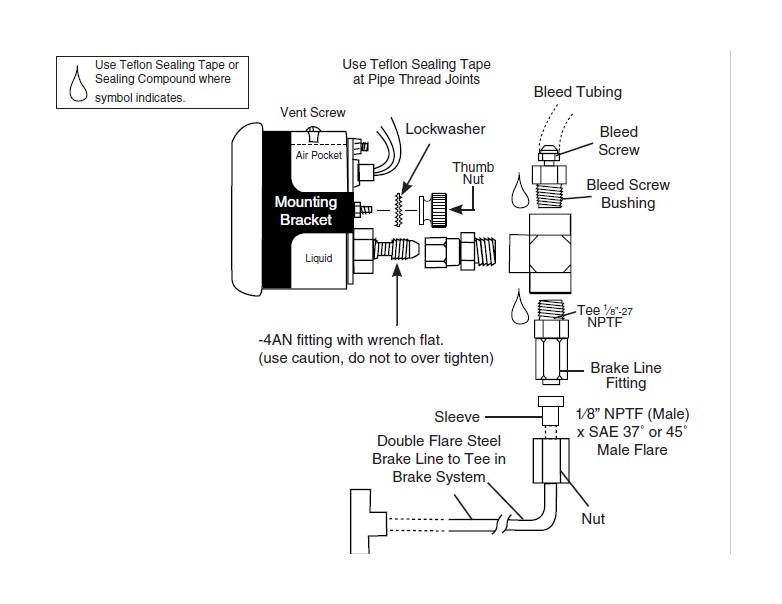
BRAKE PRESSURE GAUGES
WARNING: ONLY double flared steel brake line may be used to install this gauge. All fittings you use must have a minimum working pressure of 2000 PSI.
1. If you are not familiar with proper brake system bleeding procedure, do not install this gauge. Have a qualified mechanic do it for you.
2. Install gauge in appropriately sized dashboard hole or use under dash panels. Secure gauge with the mounting bracket provided. NOTE: If alternate gauge mounting is used other than in-dash or under dash, mounting provisions may have to be determined by the installer.
3. Secure bleed screw, bleed screw bushing, and brake line fitting to the tee provided with the gauge as shown above.
4. Secure the tee assembly from Step 3 to the gauge port. Be sure not to over tighten as this can cause the movement to loosen in the case.
5. Install a tee at the brake system location suitable for your application.
6. Install steel double flare brake line between gauge and tee.
7. Connect WHITE light wire to the dash lighting circuit or other 12V source. Connect the BLACK light wire to a suitable ground. (which applicable)
8. Bleed your gauge and brake system using standard brake bleeding procedure. If you are not familiar with brake bleeding procedure, have a qualified mechanic install this gauge for you.
FUEL PRESSURE GAUGES (W/O ISOLATOR)
WARNING: If pressure gauge is used in a fuel application, the gauge must be mounted outside of the vehicle. This will prevent the possibility of a gas fume explosion in the vehicle interior.
IMPORTANT: Both the 0-15 and 0-100 PSI Fuel Pressure Gauges must be mounted outside the vehicle unless an Auto Meter Fuel Gauge Isolator is used in conjunction with the Gauge. This is required to prevent the possibility of fire or explosion in the vehicle’s interior.
To Mount Inside of Vehicle: 0-15 PSI, 0-100 PSI: Must use full sweep electric model, or mechanical gauge with Auto Meter Fuel Pressure Isolator. See catalog or visit www.autometer.com for more information.
To Mount Outside of Vehicle:
Note: Only Auto Meter Liquid Filled and Ultra-Nite Gauges are water resistant! User should take appropriate precautions to protect all other Auto Meter instruments from getting wet. Failure to protect your gauges from water sources can result in inaccurate gauge readings or complete failure of the product. Instruments that have sustained water damage are not covered under warranty.
1. Determine best location for mounting the Fuel Pressure gauge outside of the vehicle. Mounting cup kit 5201 or 5202 is recommended for mounting gauges on vehicle’s cowling in front of windshield. Drill necessary hole and install rubber grommet where pressure line passes through sheet metal.
2. -4AN braided stainless steel tubing is recommended because of the highly flammable nature of racing fuel. Use Auto Meter kit 3227 or 3228. DO NOT USE NYLON OR COPPER TUBING WITH COMPRESSION FITTINGS.
3. Route pressure line through grommet to engine compartment, keeping line free from hot engine components or moving parts. Plumb line into vehicle’s fuel line. Be sure to use teflon sealing tape on all tapered threads for a good seal.
4. Start engine and thoroughly check for any leaks.
5. Connect WHITE light wire to dash lighting circuit or to other 12V source. Connect BLACK light wire to an engine ground.

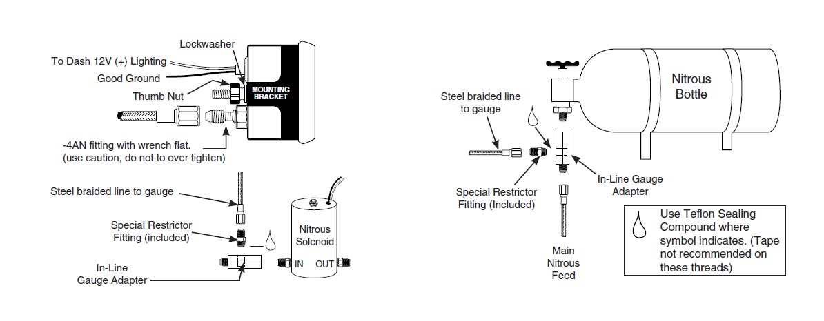
NITROUS PRESSURE GAUGES
WARNING: Use Teflon tape or sealant only where indicated. Do not use oil on threads.
WARNING: This gauge is supplied with a special restrictor fitting that. Must be installed on the braided line leading to the nitrous gauge.
WARNING: USE ONLY -4AN high pressure stainless steel braided line when installing this gauge. All fittings must have a minimum working pressure of 2000 psi.
1. If you are not familiar with nitrous oxide systems and their installations do not install this gauge. Have a qualified mechanic install it for you.
2. Determine where the nitrous gauge will be mounted and the source of the pressure (bottle outlet or nitrous solenoid inlet fitting). Then determine the length of steel braided line required. (Auto Meter offers three -4AN stainless steel braided line kits: Model #3227- 3 feet, Model #3228- 6 feet, Model #3229- 4 feet)
3. Secure the -4AN stainless steel braided line to the back of the gauge as shown in the illustration.
4. Install gauge in appropriately sized dashboard hole or use under dash panels. Secure gauge with the mounting bracket provided. NOTE: If alternate gauge mounting is used other than in-dash or under dash, mounting provisions may have to be determined by the installer.
5. Make sure the nitrous bottle valve is closed.
6. Secure an in-line gauge adapter (eg. NOS part #16770 or #16771) in a vice. Install the special restrictor fitting (supplied with gauge) in the in-line gauge adapter. Do not over tighten as this may result in stripped threads or a broken fitting.
7. Remove the main nitrous feed line from the bottle or the nitrous solenoid. Install the in-line gauge adapter with the special restrictor fitting either on the nitrous bottle or nitrous solenoid. Re-install the main nitrous feed line. Install the braided line from the nitrous gauge to the restrictor fitting.
8. Open the nitrous bottle valve.
NOTE: Test all fittings and hoses for any leakage. If any leaks are detected, determine the cause of the leak and repair. Do not operate vehicle if any leaks are detected.
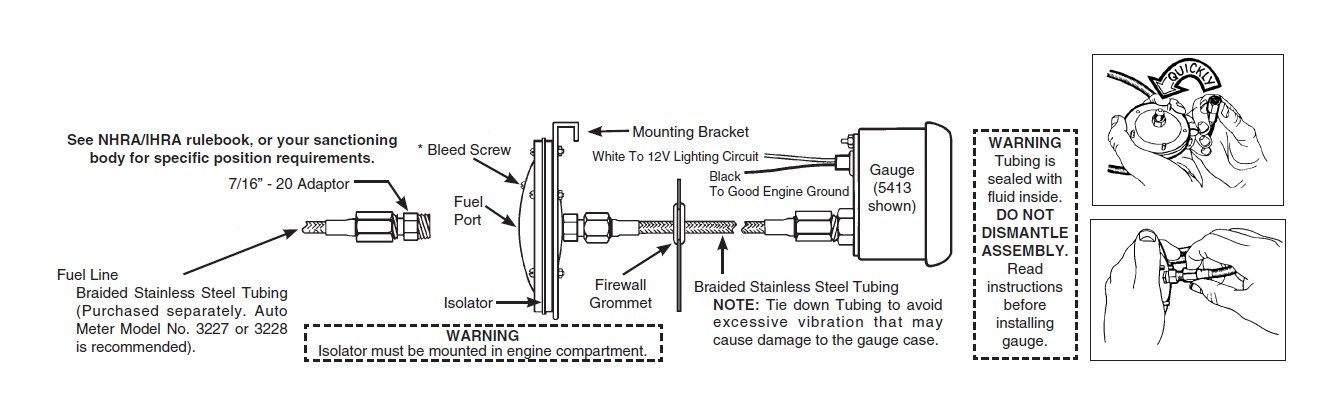
FUEL PRESSURE GAUGES (W/ ISOLATOR)
1. Install gauge and tubing assembly in an in-dash hole that is 2-1⁄16" in diameter for 2-1⁄16" models and 2-5⁄8" diameter for 2-5⁄8" models. Gauge may also be mounted in Auto Meter Accessory underdash panels. Securely mount gauge using mounting bracket provided. If mounting gauge is somewhere other than in-dash or underdash, you may be required to fabricate necessary provision.
2. Isolator must be mounted in engine compartment. (DO NOT mount on firewall per NHRA/IHRA rules.) Drill two 17⁄64" dia. holes in desired location. Mount isolator mounting bracket using the bolts, lockwashers, and nuts provided. Gauge and isolator should be mounted at the same height to insure accurate readings. If not mounted level with each other, the fluid weight will cause a slight accuracy error.
3. Drill a 7⁄8" dia. hole in firewall in line with center of mounting bracket. Route the braided tubing through hole into engine compartment.
4. With filled portion of isolator in upright position, remove dust plug. Pull braided tubing through center of isolator bracket and hold end in upright position. Remove dust plug and quickly thread braided tubing into isolator port (be careful not to spill any fluid).
NOTE: Fluid leaking from system will cause gauge to read incorrectly. If leakage occurs, fill isolator with solution of half water, half propylene glycol (antifreeze). Repeat Step 4.
5. Secure fuel pressure isolator to mounting bracket using the lockwashers and nuts provided.
6. Slit rubber grommet provided and position in firewall hole so braided tubing holds firmly in place.
7. Determine most desirable location (in line between fuel pump and carburetor) to plumb into fuel system. Thread necessary adaptor fittings into fuel side of isolator. NOTE: Use thread sealant on all pipe threads to insure a leak free seal.
8. Tee isolator into vehicle’s fuel system. We highly recommend that Auto Meter braided stainless steel tubing (Models 3227, 3228, or 3229) be used for this application.
9. With engine running, check to make sure gauge pointer moves in a smooth manner and reads the correct idling pressure.
10. Connect white light wire to dash lighting circuit or other 12V source. Connect black wire to good engine ground.
* Bleed Screw
Should excess air in the fuel side of the isolator cause erratic gauge action, bleed excess air out by just loosening the bleed screw enough to allow air passage. Do not remove the bleed screw.Tighten screw when fuel trickles out.
IMPORTANT:
Gauge and isolator should be mounted at the same height to insure accurate readings. If not mounted level with each other, the fluid weight will cause a slight accuracy error.
TUBING AND HOSE
SERVICE
For service send your product to Auto Meter in a well packed shipping carton. Please include a note explaining what the problem is along with your phone number. If you are sending product back for Warranty adjustment, you must include a copy (or original) of your sales receipt from the place of purchase.


