FREE 1 to 3-Day Delivery on Orders $149+ Details
How to Install SuperLift Replacement Front Bilstein Struts for 0-2.5 in. Lift (09-18 4WD RAM 1500) on your Dodge RAM
INTRODUCTION
Installation requires a professional mechanic. Prior to beginning, inspect the vehicle’s steering, driveline, and brake systems, paying close attention to the suspension link arms and bushings, anti-sway bars and bushings, tie rod ends, pitman arm, ball joints and wheel bearings. Also check the steering sector-to-frame and all suspension-to-frame attaching points for stress cracks. The overall vehicle must be in excellent working condition; repair or replace all worn parts.
Read instructions several times before starting. Be sure you have all needed parts and know where they install. Read each step completely as you go.
NOTES:Prior to beginning the installation, check all parts and hardware in the box with the parts list below. If you find a packaging error, contact Superlift directly. Do not contact the dealer where the system was originally purchased. You will need the control number from each box when calling; this number is located at the bottom of the part number label and to the right of the bar code.
Wheels - An 18” diameter or larger wheel must be used with this system. 17” Wheel does not work. Wheel recommendations:
* 18” diameter x 9” wide (maximum) with a maximum backspacing of 5”, or
* 20” diameter x 9” wide (maximum) with a maximum backspacing of 5-1/2”
Tires - 37” diameter x 12.50” wide
Front-end realignment is necessary.
In photos, an arrow indicates which direction is towards “front of vehicle”.
A foot-pound torque reading is given in parenthesis ( ) after each appropriate fastener.
Do not fabricate any components to gain additional suspension height.
Prior to drilling or cutting, check behind the surface being worked on for any wires, lines, or hoses that could be damaged. After drilling, file smooth any burrs and sharp edges.
Prior to operating a torch or saw, protect any heat-sensitive components located in the immediate area by covering them with a water-saturated cloth. Most undercoatings are flammable but can be extinguished using a water-filled spray bottle. Have a spray bottle and an ABC rated fire extinguisher on hand.
Paint or undercoat all metal surfaces.
Prior to attaching components, be sure all mating surfaces are free of grit, grease, excessive undercoating, etc.
A factory service manual should be on hand for reference.
Use the check-off “” found at each step to help you keep your place. Two “” denotes that one check-off box is for the driver side and one is for the passenger side.
PARTS LIST … The part number is stamped into each part or printed on an adhesive label. Identify each part and place the appropriate mounting hardware with it.
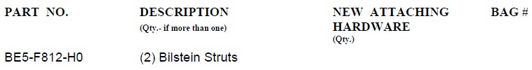
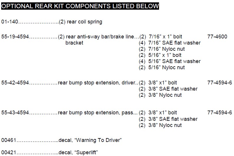
OPTIONAL REAR KIT COMPONENTS LISTED BELOW
FRONT PROCEDURE
NOTE: Save all factory components and hardware for reuse, unless noted.
1) PREPARE VEHICLE...Place vehicle in neutral. Raise front of vehicle with a jack and secure a jack stand beneath each frame rail, behind the lower control arms. Ease the frame down onto the stands, place transmission in low gear or “park”, and chock rear tires. Remove front tires.
2 ANTI-SWAY BAR LINKS…Disconnect the upper end of the anti-sway bar links from the sway bar body; leave the lower ends attached to the lower control arm.
Perform steps 3 through 5 one side at a time.
3) WHEEL SPEED SENSORS…Detach the Wheel Speed Sensor (WSS) wire at the following points, and in this order:
A) At rubber brake hose
B) At rear leg of upper control arm
C) At engine compartment side of the inner fenderwell. This attachment point is just above attachment point “B”, and is accessed by pulling the plastic inner fender outboard slightly. Point “C” is also a WSS wire plug / connector; disconnect the WSS wire here.
4) KNUCKLES…
Remove the brake caliper from the rotor and secure it away from the work area. NOTE: Do not let calipers hang from brake lines.
Loosen, but do not remove, the 4 bolts that attach the upper and lower control arms to the chassis.
Remove the front rotor from the hub. Remove the retaining axle nut from the center of the bearing hub.
Using the appropriate puller tool, disconnect the upper ball joint and outer tie rod end from the knuckle. The lower ball joint remains attached to the knuckle.
5) STRUTS… Remove the lower strut bolt. Now pivot the knuckle / lower control arm assembly downward and out of the way. Remove the three upper strut assembly bolts. Remove strut.
Repeat steps 3 through 5 on opposite side.
Perform steps 6 through 8 one side at a time.
6) STRUT DISASSEMBLY…
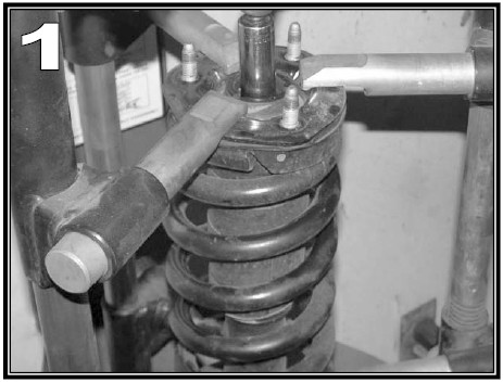
WARNING! The coil spring is preloaded, and under extreme pressure. Severe bodily injury or death may occur if the strut assembly is disassembled without using a suitable coil spring compressor. Use only a stationary commercial grade coil spring compressor as shown in [Photo 1]. Compress the coil spring until the strut body has approximately 3/8” of free movement. Remove the strut shaft-to-upper mounting plate retaining nut. The strut's upper mounting plate remains captured with the coil spring in the compressor. NOTE: Use hand tools only to remove the retaining nut; using an impact gun may damage the strut shaft.
Carefully remove the strut cylinder from the coil spring.
7) REPLACEMENT STRUTS….
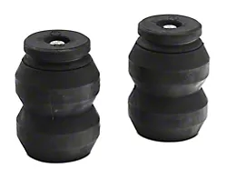
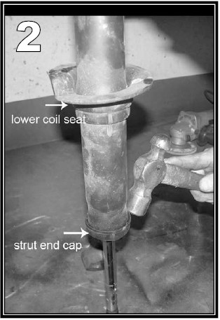
[See Photo 2] Once the factory strut has been removed, slide the bump stop off of the strut shaft, stand the strut up on its shaft end. Use a hammer and blunt-nose chisel to remove the end cap, then remove the coil spring lower seat. This seat is the only portion of the factory strut that is reused.
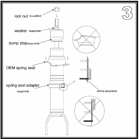
[See Diagram 3] Bilstein struts - The 5 different snap ring grooves yield these approximate lift heights... from bottom groove to top: 0", .69", 1.39", 1.69", 2.3". Position the snap ring into the appropriate groove. Remove the new bump stop from the Bilstein strut shaft.
Locate the Bilstein coil spring lower seat collar / adapter, packaged with the Bilstein strut. Slide the collar / adapter onto the strut body, followed by the factory coil spring lower seat; seat both parts against the snap ring.
Reinstall the Bilstein bump stop onto the strut shaft. Install the supplied washer (packaged with strut) onto top of the strut shaft, as shown in Diagram 3. Carefully insert the strut inside the coil, route the threaded shaft end through the upper mounting plate then rotate the strut until it aligns properly with the coil spring at both upper and lower seats. Also check for proper orientation of the strut's lower mounting ears; look at the untouched factory strut assembly on the vehicle's opposite side for comparison. Install the supplied strut shaft-to-mounting plate lock nut and tighten (34).
Slowly decompress the coil spring on the strut assembly. Make sure the coil spring seats correctly at both ends. Now remove the assembled strut from the coil spring compressor.
Install the strut assembly by first loosely attaching the strut’s upper studs to the factory frame mount using the supplied 7/16” SAE flat washers and Stover nuts; do not tighten. Now position the CV axle shaft, raise the knuckle / lower control arm then slide the CV axle shaft through the hub bearing. Do not install axle retaining nut at this time.
Attach the strut-to-lower control arm using the factory hardware. Tighten the upper hardware (45). Do not tighten the lower hardware at this time.
8) KNUCKLE, FINAL STEPS…
Connect the upper ball joint and tie rod end-to-knuckle. Reuse the factory hardware, and apply threadlocker to all. Tighten the lower ball joint nut (85), upper ball joint nut (50), CV axle shaft nut (100) and the tie rod nut (85). Do not tighten upper / lower control arm-to-chassis bolts at this time.
Install the brake rotor and caliper using the factory hardware. Apply threadlocker to caliper bolts and tighten (130).
Perform Steps 6 through 8 on opposite side.
9) ANTI-SWAY BAR LINK …Apply anti-seize to the factory anti-sway bar link threads. Reuse factory bushings and hardware. Attach anti-sway bar links to anti-sway bar body. Tighten until bushings swell slightly.
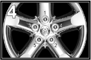
10) TIRES / WHEELS...[See Photo 4] Tighten the lug nuts in the sequence shown (130). WARNING: When the tires / wheels are installed, always check for and remove any corrosion, dirt, or foreign material on the wheel-mounting surface, or anything that contacts the wheel-mounting surface (hub, rotor, etc.). Installing wheels without the proper metal-to-metal contact at the wheel mounting surfaces can cause the lug nuts to loosen and the wheel to come off while the vehicle is in motion.
WARNING: Retighten lug nuts at 500 miles after any wheel change, or anytime the lug nuts are loosened. Failure to do so could cause wheels to come off while vehicle is in motion.
Lower vehicle to the floor. The suspension is now supporting vehicle weight.
11) TORQUE CONTROL ARMS AND STRUTS…Tighten the lower control arm bolts (110). Tighten the lower strut bolts (155). Tighten the upper control arm bolts (130).
12) CLEARANCE CHECK...Raise the vehicle back onto jack stands and secure as per step 1. With the suspension “hanging” at full extension travel, cycle steering lock-to-lock and check all components for proper operation and clearances. Pay special attention to the clearance between the tires / wheels and knuckles, brake hoses, wiring, etc.
Lower the vehicle to the floor.
OPTIONAL REAR PROCEDURE
13) PREPARE VEHICLE…Before raising the rear of the vehicle:
Disconnect the upper end of the track bar. Loosen, but do not remove, the track bar at the driver side axle mount.
Disconnect the upper ends of the anti-sway bar links where they attach to the frame.
Disconnect the brake line mount and wheel speed sensor. Both are located on the frame, behind the coil springs' upper mount.
Remove the bolt securing the wire hanger bracket that captures the parking brake cables. This hanger is bolted to the driver side, lower suspension link arm. Retain hardware.
14) RAISE REAR OF VEHICLE…Position a jack beneath the center of the rear axle then raise rear of vehicle. Secure jack stands beneath the frame rails just forward of the rear springs. Chock front tires to prevent any possibility of movement. Remove rear tires.
SHOCKS AND COIL SPRINGS…Remove shock absorbers. Lower the axle just enough to allow removal of coil springs.
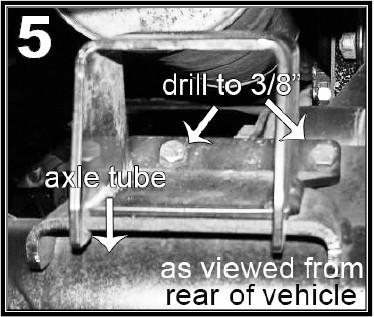
15) BUMP STOPS…[See Photo 5]
Position the Superlift passenger side bump stop bracket (SL# 55-24-4594), as shown, on top of the factory bump stop pad, located on top of the axle tube, just inboard of the coil springs. The “hooks” on the back side of the Superlift bracket capture the underside of the factory bump stop pad. Center the Superlift bracket on the pad then using the holes in the Superlift bracket as a template, drill two holes through the factory pad for the 3/8” mounting hardware. Insert the supplied 3/8” x 1” bolts (installed from top), flat washers (on nut side), and Nyloc nuts. Tighten (30).
The Superlift driver side bump stop bracket (SL# 55-23-4594) attaches through pre-existing holes in the factory pad. It uses the same hardware as the passenger side.
16) COIL SPRINGS AND SHOCKS…Install Superlift coil springs and shock absorbers using the factory hardware and supplied shock bushings and sleeves. Do not tighten. Apply shock decals.
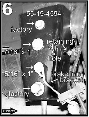
17) BRAKE LINE / ANTI-SWAY BAR BRACKET…[See Photo 6] Perform this step one side at a time. The WSS wire is clipped to the front face of the factory anti-sway bar link’s frame bracket. Detach WSS clip from the bracket.
Position the Superlift brake line / anti-sway bar relocation bracket (SL# 55-19-4594) over the factory bracket. Use the factory hardware in the top hole, and the supplied 7/16” x 1” bolt, flat washers (on both nut and bolt head sides) and Nyloc nut in the next hole down. Use the supplied 5/16” x 1” bolt, flat washers (on both nut and bolt head sides) and Nyloc nut to attach the factory brake line bracket - to - Superlift bracket. Tighten the 7/16” hardware (50). Tighten the 5/16” hardware (200 in. Lbs.). Tighten the factory hardware (top hole) (23).
Loosely attach the upper end of the anti- sway bar link to the Superlift bracket using factory hardware. Do not tighten.
The WSS wire clip, detached in the first step, plugs into a hole in the front face of the Superlift bracket, as shown in Photo 15.
[See Photo 6] There are three more WSS wire clips per side. Lubricate all then feed the WSS wire up and along the brake hose / line so the end result is as shown.
Replace the bolt securing the wire hanger bracket that captures the parking brake cables. This hanger is bolted to the driver side, lower suspension link arm.
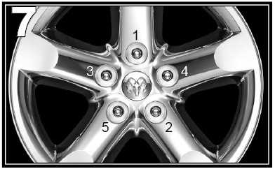
18) TIRES / WHEELS...[See Photo 7]
Tighten the lug nuts in the sequence shown (130). WARNING: When the tires / wheels are installed, always check for and remove any corrosion, dirt, or foreign material on the wheel-mounting surface, or anything that contacts the wheel-mounting surface (hub, rotor, etc.). Installing wheels without the proper metal-to-metal contact at the wheel mounting surfaces can cause the lug nuts to loosen and the wheel to come off while the vehicle is in motion.
WARNING: Retighten lug nuts at 500 miles after any wheel change, or anytime the lug nuts are loosened. Failure to do so could cause wheels to come off while vehicle is in motion.
Lower vehicle to the floor. The suspension is now supporting vehicle weight.
Reconnect the upper end of the track bar. Tighten.
19) REAR HARDWARE TIGHTENING SEQUENCE…
Shock absorbers (100).
Anti-sway bar links to the Superlift brackets (80).
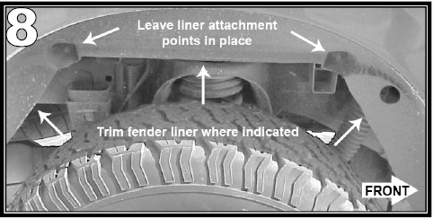
20) REAR WHEEL LINER…[See Photo 8] On trucks equipped with the plastic rear wheel liners the liner may have to be trimmed to minimize contact to the tire. Trim the liner horizontally on the angled face above the area of contact. Leave the two fasteners intact and trim the liner at an angle on each end to meet the bottom of the liner. Paint any exposed surfaces black for best appearance.
21) FINAL CLEARANCE AND TORQUE CHECK...With vehicle on floor, cycle steering lock-to-lock and inspect the tires / wheels, and the steering, suspension, and brake systems for proper operation, tightness, and adequate clearance.
22) FOUR WHEEL DRIVE…Activate four-wheel drive system and check for proper engagement.
23) HEADLIGHTS...Readjust headlights to proper setting.
24) SUPERLIFT WARNING DECAL...Install the WARNING TO DRIVER decal on the inside of the windshield, or on the dash, within driver’s view.