FREE 1 to 3-Day Delivery on Orders $149+ Details
How to Install PIAA LP530 3.5 in. Round LED Back-up Lights - Flood Beam - Pair on your Silverado
1. Lamp installation preparations and temporary setup
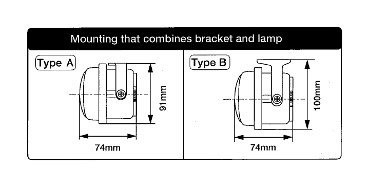
• Using the holes in the lamp bracket, the height from the lamp body to the installation surface can be adjusted. Depending on the top and bottom measurements as well as shape.
• In case the mounting surface is not flat position or is not enough space of it' s surface, please make sure to fix the lamp stably by using double-stick tape and screws(sell separately).
2. Lamp installation preparations and temporary setup
When you have decided the installation method ......
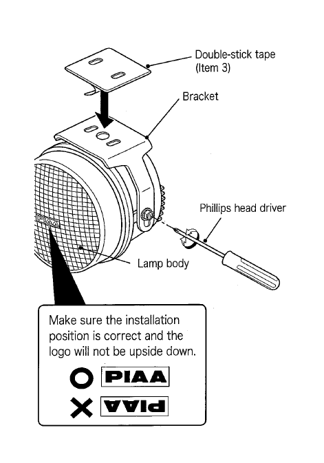
(1) Rearrange the bracket according to your needs, and apply double-stick tape (Item 3) and one-side tape as shown in the diagram below.
(2) Hold the lamp up to where it will be installed on the vehicle. Verify the gap between the lamp and surrounding obstacles.
CHECK
• Make sure the lamp can be adjusted up and down (beam must be adjusted so that it shines at least 40m ahead of the vehicle.) If it cannot be adjusted, it must be re-installed.
• There must be between 30mm to 35mm on either side of the lamp to allow for proper adjustment.
• If using a screw, make sure there is adequate space between the bracket and the lamp(where screw will be inserted).
CAUTION
• When using a bracket available on the market, make sure the bolts you remove from the vehicle does not hinder its performance.
• Do not install on an unstable location, it may come lose while driving. This may affect the overall life of the bulb. In addition it may damage the vehicle or the main body of the lamp. Make sure you install the lamp on a stable and secure location.
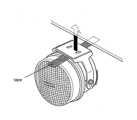
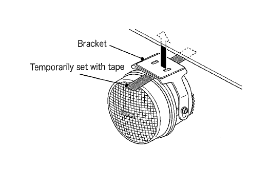
• Temporarily set the bracket with tape.
CAUTION
• Make sure to set position properly before permanently setting the lamp. Also, thoroughly clean the surface of the installation position beforehand.
• Make sure to remove the tape glue on the vehicle body after installation.
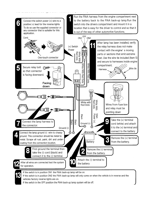
3. Relay Harness Installation Sequence
4. Lamp Installation Procedures
1. Temporarily set the bracket with tape and then mark the correct possition.
2. Remove the lamp harness bullet connectors and take out the lamp.
3. Install the lamp according to the marking made prior to installation.
If using only the double-stick tape.
Peel the protective sheet from the double-stick tape (Item 3) and apply.
CAUTION
• When using the double-stick tape, clean the surface where tape will be applied. Use a clean cloth or sponge and make sure dirt, grease, wax etc., are completely removed. If substances cannot be removed, it may not adhere properly. In particular, avoid using leather wax, tire wax and also any type of organic solvent.
• When used in low temperatures, the adhesive substance tends to lose its strength. Use a drier or simply warm up the adhesive surface before applying. When using a drier, avoid moving it too close to the bumper as it may cause it to deform.
• After installation, avoid excess speeds and do not wash for 1 to 2 days.
• If applied incorrectly, a special double-stick tape is available at your local PIAA dealer.
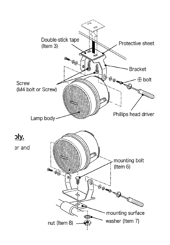
If using screws(M4 bolt or screw) to fix lamp stably
(1) Loosen ( ) bolt with Philip' s head driver and remove the bracket from the lamp.
(2) Peel off the protective sheet from the double-stick tape and apply it to the bracket.
(3) Fix the bracket in place with the screws.
(4) Install the lamp onto the bracket.
If using M10 bolt to fix lamp stably.
(1) Loosen ( ) bolt with Philip' s head driver and remove the bracket from the lamp.
(2) Fix the bracket in place with the bolt.
(3) Install the lamp onto the bracket.
5. Troubleshooting
1 After installation, if the lamp does not activate
→ Check the wiring and make sure there are no faulty or irregular connections .
● If the switch illumination does not light up.
→ Verify the ( ) wire from the switch is properly connected. If it is not correctly connected it will not activate.
→ Verify the fuse located on the vehicle’s wiring system. (the switch’s ( ) wire should be connected to the fuse box). If it is burned out, connect it to another circuit.
→ If the switch itself is faulty, the same symptoms may exist. We recommend that the entire switch unit be replaced.
→ Check the fuse for the switch harness. If it is burned out, follow instructions indicated in [ 3 Fuse replacement Procedures].
● The switch illumination lights up but when operating does not work.
→ Check the connecting (-) cord to the body earth.
→ There may be cases where each terminal related to specific sections may be incorrectly connected. Check for any lose wires and also for dirt or grime.
→ Check the switch operation If an abnormality is found, replace it accordingly.
2 If the LED suddenly fails to light up …
→ Check the fuse located on the vehicle’s wiring system. If it is burned out, replace accordingly.
→ Check the fuse for the switch harness. If it is burned out, follow instructions indicated in [ 3 Fuse replacement Procedures].
→ There may be cases where each terminal related to specific sections may be incorrectly connected. Check for any lose wires and also for dirt or grime.
→ Check the switch operation if an abnormality is found, replace it accordingly.
3 Fuse replacement procedures
→ A short circuit may have occurred. Check the wiring system. If any type of damage is found replace accordingly. (Non-replacement may pose a potential danger) (Short circuits are mainly caused when wires are caught in the assembly or when there is a gap in the sleeve connected to the lamp harness).