 FREE 1 to 3-Day Delivery on Orders $149+ Details
How to Install SuperLift 6 in. Suspension Lift Kit w/ Superide Shocks (06-08 4WD RAM 1500) on your Dodge RAM
INTRODUCTION
Installation requires a professional mechanic. Prior to beginning, inspect the vehicle’s steering, driveline, and brake systems, paying close attention to the suspension link arms and bushings, anti-sway bars and bushings, tie rod ends, pitman arm, ball joints and wheel bearings. Also check the steering sector-to-frame and all suspension-to-frame attaching points for stress cracks. The overall vehicle must be in excellent working condition; repair or replace all worn parts. If your vehicle is equipped with the factory TRX package, order Superlift preload spacer kit box 4580.
Read instructions several times before starting. Be sure you have all needed parts and know where they install. Read each step completely as you go.
NOTES:
Prior to beginning the installation, check all parts and hardware in the box with the parts list below. If you find a packaging error, contact Superlift directly. Do not contact the dealer where the system was originally purchased. You will need the control number from each box when calling; this number is located at the bottom of the part number label and to the right of the bar code.
Wheels - An 18” diameter or larger wheel must be used with this system. Wheel recommendations:
* 18” diameter x 9” wide (maximum) with a maximum backspacing of 5”, or
* 20” diameter x 9” wide (maximum) with a maximum backspacing of 5-1/2”
Tires - 37” diameter x 12.50” wide
Front-end realignment is necessary.
In photos, an arrow indicates which direction is towards “front of vehicle”.
A foot-pound torque reading is given in parenthesis ( ) after each appropriate fastener.
Do not fabricate any components to gain additional suspension height.
Prior to drilling or cutting, check behind the surface being worked on for any wires, lines, or hoses that could be damaged. After drilling, file smooth any burrs and sharp edges.
Prior to operating a torch or saw, protect any heat-sensitive components located in the immediate area by covering them with a water-saturated cloth. Most undercoatings are flammable but can be extinguished using a water-filled spray bottle. Have a spray bottle and an ABC rated fire extinguisher on hand.
Paint or undercoat all metal surfaces.
Prior to attaching components, be sure all mating surfaces are free of grit, grease, excessive undercoating, etc.
A factory service manual should be on hand for reference.
Use the check-off “” found at each step to help you keep your place. Two “” denotes that one check-off box is for the driver side and one is for the passenger side.
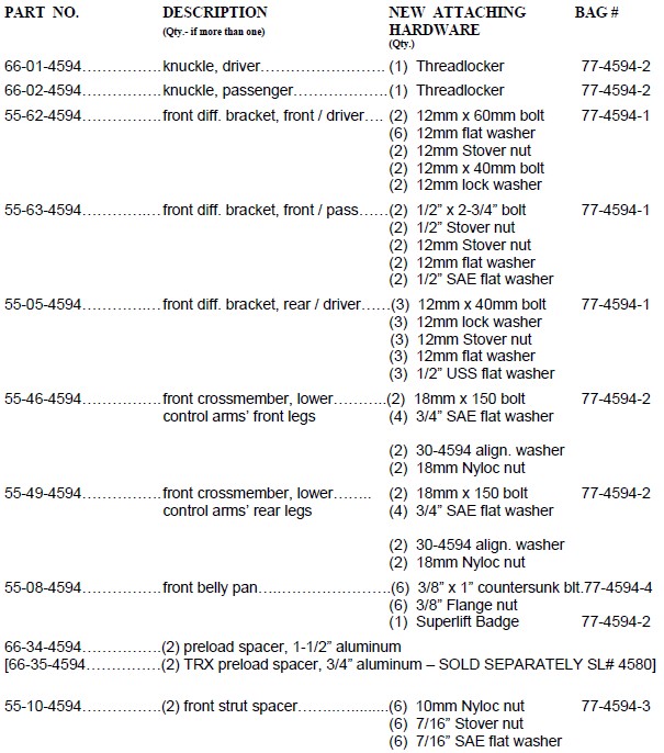
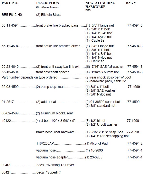
PARTS LIST … The part number is stamped into each part or printed on an adhesive label. Identify each part and place the appropriate mounting hardware with it.
FRONT PROCEDURE
NOTE: Save all factory components and hardware for reuse, unless noted.
1) PREPARE VEHICLE...Place vehicle in neutral. Raise front of vehicle with a jack and secure a jack stand beneath each frame rail, behind the lower control arms. Ease the frame down onto the stands, place transmission in low gear or “park”, and chock rear tires. Remove front tires.
2) FRONT DIFFERENTIAL SKID PLATE AND DRIVESHAFT…If equipped, remove the factory front differential skid plate and discard. Disconnect the front driveshaft from the differential then secure driveshaft up and out of the way.
3) ANTI-SWAY BAR LINKS…Disconnect the upper end of the anti-sway bar links from the sway bar body; leave the lower ends attached to the lower control arm.
Perform steps 4 through 7 one side at a time.
4) WHEEL SPEED SENSORS…Detach the Wheel Speed Sensor (WSS) wire at the following points, and in this order:
A) At rubber brake hose
B) At rear leg of upper control arm
C) At engine compartment side of the inner fenderwell. This attachment point is just above attachment point “B”, and is accessed by pulling the plastic inner fender outboard slightly. Point “C” is also a WSS wire plug / connector; disconnect the WSS wire here.
5) KNUCKLES…
Remove the brake caliper from the rotor and secure it away from the work area. NOTE: Do not let calipers hang from brake lines.
Remove the front rotor from the hub. Remove the retaining nut from the center of the bearing hub.
Loosen, but do not remove, the upper control arm bolts.
Using the appropriate puller tool, disconnect the upper and lower ball joints and outer tie rod end from the knuckle. Remove knuckle. The wheel speed sensor wire remains on the factory knuckle for now.
6) STRUTS… Loosen, but do not remove, the lower control arm bolts. Remove the lower strut bolt. Remove the three upper strut assembly bolts. Remove strut.
7) LOWER CONTROL ARMS…Remove the lower control arm’s two alignment cam bolt assemblies then remove the lower control arm.
Repeat steps 4 through 7 on opposite side.
8) REAR CROSSMEMBER…Remove the factory lower control arms’ rear crossmember.
9) DIFFERENTIAL…Disconnect all electrical and vacuum lines from differential. Unbolt front driveshaft and secure it up and out of the way. Support the differential and remove all differential-to-frame mounting hardware. Remove differential assembly.
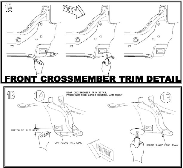
10) TRIMMING FRONT AND REAR / LOWER CONTROL ARM MOUNT…[See Photo 1 and 1A]
The front driver and passenger side lower control arm
mount must be trimmed. Measure down 1” from the bottom edge of the slot and mark a line parallel to the slot. Cut the frame through the front side only along the marked line using a cut-off wheel or Sawz-all. After cutting, clean and paint all exposed areas.
The passenger side factory rear / lower control arm mount must be trimmed as shown. Measure down from the bottom edge of the slot and mark a line parallel to the slot. Cut the frame through the front side only along the marked line using a cut-off wheel or Sawz-all. After cutting, clean and paint all exposed areas.
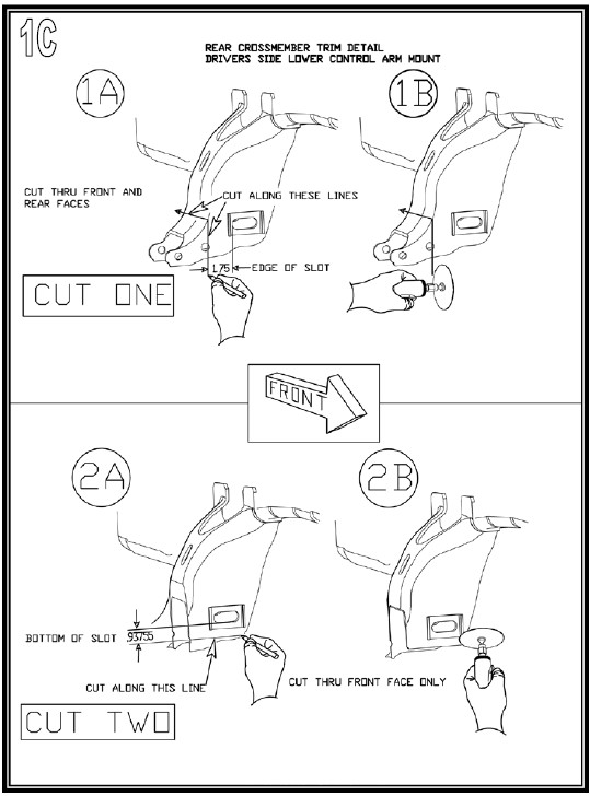
The driver side factory rear / lower control arm mount must be trimmed as shown. Measure to the inside 1-3/4” from inside edge of slot and mark a line perpendicular to the bottom edge of the slot. Cut the frame through all sides along the marked lines (front, top and back sides) using a cut-off wheel or Sawz-All. After the first cut, measure down from the bottom edge of the slot 15/16” and mark and line parallel with the bottom edge of the slot on the front side of the factory mount. Cut the frame through the front side only along the marked line using a cut-off wheel or Sawz-All. After cutting, clean and paint all exposed areas.
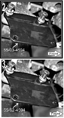
11) DIFFERENTIAL BRACKETS…[See Photo 2]
Loosely attach the driver side / front differential bracket (SL# 55-62-4594) to the frame using the supplied 12mm x 40mm bolts, lock washers, and flat washers. Do not tighten.
[See Photo 3] Loosely attach the driver side / rear differential bracket (SL# 55-05-4594) to the frame using the supplied 12mm x 40 bolts, lock washers, and flat washers. Do not tighten.
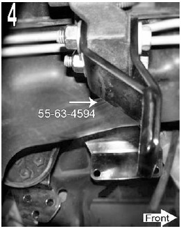
[See Photo 4] Loosely attach the passenger side differential bracket (SL# 55-63-4594) to the frame using the factory bolts and the supplied 12mm flat washers and Stover nuts. Do not tighten.
12) CV AXLES…On each side, disconnect the inner CV axle assembly from the differential. Use two pry bars, positioned between the inner CV and the differential housing, to free the axles.
13) INSTALL DIFFERENTIAL AND SUPERLIFT REAR CROSSMEMBER (SL# 55-49-4594)…
Position the differential in the frame - Loosely attach the differential to the Superlift driver side / front bracket using the supplied 12mm x 60mm bolts, flat washers (on both nut and bolt head sides) and Stover nuts. Do not tighten. The differential is attached to the remaining Superlift brackets in later steps.
Superlift rear crossmember, passenger side - Raise the passenger side of the differential housing which will allow you to mate the passenger side of the Superlift crossmember - to - frame. Insert the supplied 18mm x 150mm bolt and flat washer from the front, through the factory mount crossmember. Position the 2” x 1-1/2” x 3/16” thick lockout tab onto the bolt; the tab seats in what was the factory rear cam washer’s location. Install the supplied flat washer then the supplied 18mm Nyloc nut. Do not tighten. Note the crossmember goes inside of the factory mount.
Superlift rear crossmember, driver side - Position the driver side of the Superlift crossmember into the frame. Insert the supplied 18mm x 150mm bolt and flat washer from the front, through the factory mount and crossmember. Position the 2” x 1-1/2” x 3/16” thick lockout tab onto the bolt; the tab seats in what was the factory rear cam washer’s location. Install the supplied flat washer then the supplied 18mm Nyloc nut. Do not tighten. Note the crossmember goes inside of the factory mount.
Differential - to - Superlift passenger side bracket - Loosely attach using the supplied 1/2” x 2-3/4” bolts, flat washers (on both nut and bolt head sides) and Stover nuts. Do not tighten.
Differential - to - Superlift driver side / rear bracket - Attach using the three factory differential bolts and the supplied nuts that were earlier removed from the factory rear crossmember.
Tighten all differential hardware to (70) in the order listed: the four bolts securing the driver side / front bracket ; the four bolts securing the passenger side bracket; the six bolts securing the driver side / rear bracket. Leave the two crossmember - to - frame bolts loose at this time.
Insert the 5/16” vacuum line adapter (SL# 23-3205) and new vacuum line (SL# 18-9690). Reconnect the electrical lines; retaining clips may need to be removed to create enough “slack” to reconnect.
14) SUPERLIFT FRONT CROSSMEMBER (SL# 55-46-4594)…
Position the Superlift crossmember into the frame; make sure the tab with the skid plate holes are towards the rear of the vehicle. Insert the supplied 18mm x 150mm bolt and flat washer from the front, through the factory mount and crossmember. Position the 2” x 1-1/2” x 3/16” thick lockout tab onto the bolt; the tab seats in what was the factory rear cam washer’s location. Install the supplied flat washer then the supplied 18mm Nyloc nut. Do not tighten. Note the crossmember goes inside of the factory mount.
15) FRONT DRIVESHAFT…[See Photo 5] Install driveshaft spacer (SL# 66-13-4594) between the differential mounting flange and the driveshaft using the supplied 12mm x 50mm bolts. Apply threadlocker to the bolts before installation. Tighten (85).
Perform steps 16 through 20 one side at a time.
16) LOWER CONTROL ARMS…
NOTE: It is possible to incorrectly install the driver side lower control arm on the passenger side of the vehicle, and vice-versa. When the control arm is located properly, the sway bar links will be positioned towards front of vehicle, and the lower ball joint stud points down.
Loosely install the factory lower control arm reusing the factory cam bolts assemblies. Insert bolts from the
front with the cam lobes in the upright / centered position. Do not tighten.
17) SUPERLIFT® COIL SPRING SPACERS…
Locate the factory strut assembly. Use a paint marker to scribe three vertically aligned indexing marks on the outboard side of the assembly. Mark: 1) the outboard facing side of the upper strut mounting plate, 2) the top (exposed) coil spring wrap, 3) the center of the lower strut eye mount.
17a) STRUT DISASSEMBLY…
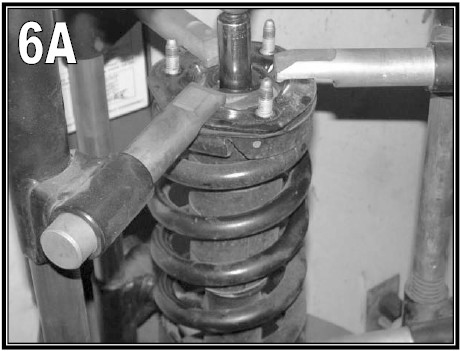
WARNING! The coil spring is preloaded, and under extreme pressure. Severe bodily injury or death may occur if the strut assembly is disassembled without using a suitable coil spring compressor. Use only a stationary commercial grade coil spring compressor as shown in [Photo 6a]. Compress the coil spring until the strut body has approximately 3/8” of free movement. Remove the strut shaft-to-upper mounting plate retaining nut. The strut's upper mounting plate remains captured with the coil spring in the compressor. NOTE: Use hand tools only to remove the retaining nut; using an impact gun may damage the strut shaft.
Carefully remove the strut cylinder from the coil spring.
NOTE: Inspect the strut assembly for any damage or fluid leakage. Replace if necessary.
IF REPLACEMENT BILSTEIN STRUTS WERE PURCHASED, SKIP TO STEP 17b.
Position the strut cylinder back into the compressed coil spring. Align the indexing marks on the lower strut eye mount and the coil spring.
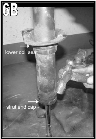
[See Photo 6b] Assemble the top end of the strut in this order:
A) Position the spring isolator on top of the coil spring.
B) Position the supplied 1-1/2” coil spacer (SL# 66-09-4594) or for TRX4 models position the 3/4” coil spacer (SL# 66-33-4594) on top of the isolator.
C) Position the strut upper mounting plate on top of the Superlift® coil spacer. Align the plate indexing mark with the indexing marks on the coil spring and shock eye.
D) Install the factory bushing half, washer, and nut.
E) Tighten the strut mounting stem (20).
Slowly decompress the coil spring on the strut assembly while ensuring that the coil spring remains seated correctly in its lower seat and that all three index marks remain aligned.
Slowly decompress the coil spring on the strut assembly. Make sure that the spring is seated correctly into the strut assembly and aligned with the previously scribed index mark on the upper strut mounting plate.
Position the strut spacer (SL# 55-10-4594) onto the top of the factory strut using the factory hardware. Tighten (45).
Install the strut assembly by first loosely attaching the strut’s upper studs to the factory frame mount using the supplied 7/16” SAE flat washers and Stover nuts; do not tighten. Now raise the lower control arm, and insert the factory lower strut hardware. Tighten the upper hardware (45). Do not tighten the lower strut hardware at this time.
IF REPLACEMENT BILSTEIN STRUTS WERE NOT PURCHASED, SKIP TO STEP 18.
17b) REPLACEMENT STRUTS….
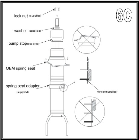
[See Photo 6b] Once the factory strut has been removed, slide the bump stop off of the strut shaft, stand the strut up on its shaft end. Use a hammer and blunt-nose chisel to remove the end cap, then remove the coil spring lower seat. This seat is the only portion of the factory strut that is reused.
[See Diagram 6c] Bilstein struts - The 5 different snap ring grooves yield these approximate lift heights... from bottom groove to top: 0", .69", 1.39", 1.69", 2.3". Position the snap ring into the appropriate groove. (6” kits should typically use the top groove.) Remove the new bump stop from the Bilstein strut shaft.
Locate the Bilstein coil spring lower seat collar / adapter, packaged with the Bilstein strut. Slide the collar / adapter onto the strut body, followed by the factory coil spring lower seat; seat both parts against the snap ring.
Reinstall the Bilstein bump stop onto the strut shaft. Install the supplied washer (packaged with strut) onto top of the strut shaft, as shown in Diagram 3. Carefully insert the strut inside the coil, route the threaded shaft end through the upper mounting plate then rotate the strut until it aligns properly with the coil spring at both upper and lower seats. Also check for proper orientation of the strut's lower mounting ears; look at the untouched factory strut assembly on the vehicle's opposite side for comparison. Install the supplied strut shaft-to-mounting plate lock nut and tighten (34).
Slowly decompress the coil spring on the strut assembly. Make sure the coil spring seats correctly at both ends. Now remove the assembled strut from the coil spring compressor.
Install the strut assembly by first loosely attaching the strut’s upper studs to the factory frame mount using the supplied 7/16” SAE flat washers and Stover nuts; do not tighten. Now position the CV axle shaft, raise the knuckle / lower control arm then slide the CV axle shaft through the hub bearing. Do not install axle retaining nut at this time.
Attach the strut-to-lower control arm using the factory hardware. Tighten the upper hardware (45). Do not tighten the lower hardware at this time.
Repeat step on opposite side
18) CV AXLES…Insert the inner CV axle shaft into the differential then push firmly to engage CV axle shaft retaining ring.
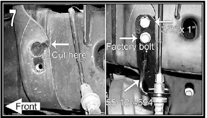
19) BRAKE LINE / HOSE RELOCATION…[See Photo 7]
Locate where the upper end of the rubber brake hose passes through the frame and connects to a metal brake line. Use the appropriate tool (ex: cut-off wheel) to cut a notch in the frame to allow removal of the brake hose / line connector. Take care NOT to damage the brake line / hose. Remove the brake line bracket bolt then free the line / hose connector from frame.
There are a couple of bends in the metal line, just above the line / hose connector. Carefully re-form (straighten-out) the bends, as needed, to allow the factory brake line bracket to mate with the Superlift bracket. DO NOT kink the line. Attach the factory brake line bracket to the Superlift brake line bracket (SL# 55-12-4594 driver and 55-11-4594 passenger) using the supplied 1/4” x 3/4” bolt and Nyloc nut. Attach Superlift brake line bracket - to - frame using the supplied 3/8” x 1” bolt and Flange nut in the top hole and the factory hardware in the bottom hole. Tighten the 3/8” hardware (30). Tighten the factory and 1/4” hardware (95 In. Lbs.)
20) SUPERLIFT KNUCKLE INSTALLATION…
Remove the bolt that secures the Wheel Speed Sensor (WSS) wire mounting bracket to the factory knuckle. Attach this bracket to the Superlift knuckle in the same orientation as factory.
Remove the hub assembly and dust shield from the factory knuckle. Do not disconnect the WSS wire from the hub assembly.
Position the factory hub assembly and dust shield onto the new Superlift knuckle (SL# 66-01-4594 driver and 66-02-4594 passenger). The hub must be positioned with
the WSS wire routed forward and inside the relief machined into the knuckle face. Apply threadlocker to the factory hardware then fasten hub assembly and dust shield to the Superlift knuckle. Tighten (95).
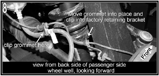
[See Photo 8] Route the WSS wire to the mounting bracket on the knuckle, as shown. The rubber grommet on the WSS wire must be shifted. Lubricate the WSS wire and rubber grommet with a detergent-based cleaner (ex: Windex, Formula 409), which allows the WSS wire to slide easily through the rubber grommet. When satisfied with routing, insert the WSS wire / rubber grommet into the mounting bracket.
Install knuckle onto vehicle. Attach the lower ball joint first then slide the CV axle shaft through the hub bearing. Next connect the upper ball joint and tie rod end. Reuse the factory hardware, and apply threadlocker to all. Tighten the lower ball joint nut (85), upper ball joint nut (50), CV axle shaft nut (100) and the tie rod nut (85).
Install the brake rotor and caliper using the factory hardware. Apply threadlocker to caliper bolts. Tighten (130).
Route / reattach the Wheel Speed Sensor (WSS) wire at the following points, and in this order. Again, it will be necessary to lubricate the grommets / WSS wire to allow movement:
A) At rubber brake hose
B) At rear leg of upper control arm
C) Reconnect the WSS wire plug / connector. Do not reattach the connector to the inner fenderwell.
21) ANTI-SWAY BAR LINK EXTENSIONS…Apply anti-seize to the factory anti-sway bar link threads. Install three 7/16” SAE washers per side then install the anti-sway bar link extensions (SL# 55-23-4640). Reuse factory bushings and hardware. Attach anti-sway bar links to anti-sway bar body. Tighten until bushings swell slightly.
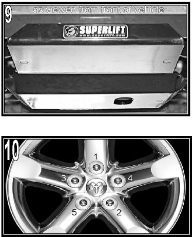
22) BELLY PAN…[See Photo 9] Attach the belly pan (SL# 55-08-4594) to the Superlift lower control arm crossmembers using the six supplied 3/8” x 1” countersunk bolts and Flange nuts. Tighten (30). Clean the front lip of the belly pan with the supplied alcohol pad and install the Superlift badge.
Tighten all four crossmember - to - frame bolts (75).
23) TIRES / WHEELS...[See Photo 10] Tighten the lug nuts in the sequence shown (130).
WARNING: When the tires / wheels are installed, always check for and remove any corrosion, dirt, or foreign material on the wheel-mounting surface, or anything that contacts the wheel-mounting surface (hub, rotor, etc.). Installing wheels without the proper metal-to-metal contact at the wheel mounting surfaces can cause the lug nuts to loosen and the wheel to come off while the vehicle is in motion.
WARNING: Retighten lug nuts at 500 miles after any wheel change, or anytime the lug nuts are loosened. Failure to do so could cause wheels to come off while vehicle is in motion.
Lower vehicle to the floor. The suspension is now supporting vehicle weight.
24) TORQUE CONTROL ARMS AND STRUTS…Tighten the lower control arm bolts (110). Tighten the lower strut bolts (155). Tighten the upper control arm bolts (130).
25) CLEARANCE CHECK...Raise the vehicle back onto jack stands and secure as per step 1. With the suspension “hanging” at full extension travel, cycle steering lock-to-lock and check all components for proper operation and clearances. Pay special attention to the clearance between the tires / wheels and knuckles, brake hoses, wiring, etc.
Lower the vehicle to the floor.
REAR PROCEDURE
26) PREPARE VEHICLE... Raise rear of vehicle with a floor jack positioned under the rear axle. Place jack stands under the frame rails, a few inches in front of the rear springs’ front hangers. Ease the jack down until the frame is resting on the stands. Keep a slight load on the jack. Chock front tires to prevent accidental movement.
27) DISASSEMBLY...Remove the tires. Remove the shock absorbers.
28) SPRING PACK DISASSEMBLY…
Remove spring to axle U-bolts and move axle several inches away from springs.
Place C-clamps approximately six inches on either side of the leaf springs center bolt. Pinch the tie bolt head (the portion that was located in the spring perch) with a pair of pliers, then remove the tie bolt nut. Once the nut has been removed, loosen the C-clamps. NOTE: Be cautious when releasing the C-clamps; the springs are under load and will "spring" apart when released.
The factory leaf springs have a roll pin installed through the leaf pack. This will have to be removed. Turn the bottom leaf (axle-side leaf) 45 degrees, then with a dead-blow hammer strike the leaf until it is free from the leaf spring pack. The roll pin will stay attached to the bottom leaf. Use a punch and remove the roll pin from the leaf.
29) SPRING PACK ASSEMBLY…
On each side, insert the add-a-leaf between the number one and number two leaf from the axle side, in the proper pyramid order. Align the 3/8” hole in the add-a-leaf with the center bolt hole in the spring pack.
Recompress the pack with the C-clamp, not the center bolt, to avoid stripping the bolt or nut threads. Once the spring is compressed, insert the 3/8” x 5” center bolt through the aluminum block (SL# 66-02-4599) and the leaf spring pack. Tighten the center bolt nut (45). Once tightened, trim excess bolt. Remove the C-clamps.
30) REATTACHING THE AXLE…
Clean spring pads of all debris.
Using the floor jack(s), mate the springs to their pads, be sure that the center bolt heads seat properly. Install the new Superlift U-bolts and factory U-bolt plate. Evenly torque the U-bolts using an "X" tightening sequence (85).
31) BUMP STOPS…
Remove the two bolts securing the factory bump stop to the frame.
Position the new Superlift bump stop bracket (SL# 55-03-4599) into the factory bump stop location and secure with the factory hardware (30).
Reattach the factory bump stop to the Superlift bracket using the supplied 3/8” x 1” bolts, washers, and Nyloc nut (30).
32) SHOCK ABSORBERS…Install the new Superlift lift shock absorbers using the factory hardware (100).
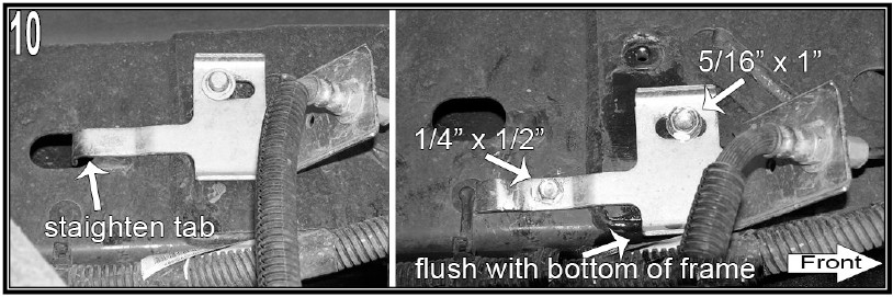
33) BRAKE LINE RELOCATION…[See Photo 10]
Unbolt the two bolts holding the brake line bracket to the inside of the frame rail on the driver’s side of the vehicle.
Straighten the bracket’s locating tab so that the bracket will fit flat on the frame.
Move the brake line bracket down until the bottom edge of the bracket is flush with the bottom edge of the frame. Mark the frame and drill to 19/64”. Insert the supplied 5/16” x 1” self-tapping bolt. (125 in. lbs.)
With the brake line bracket in place, drill a 15/64” hole though the bracket and the frame in the middle of the bracket’s locating “arm” as shown. Insert the supplied 1/4” x 1/2” self-tapping bolt. (70 in. lbs.)
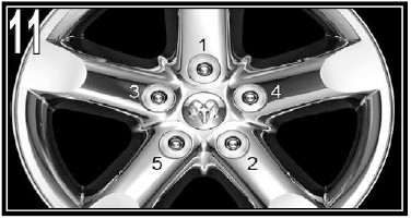
34) TIRES / WHEELS...[See Photo 11] Install tires and wheel. Tighten the lug nuts in the sequence shown (130). WARNING: When the tires / wheels are installed, always check for and remove any corrosion, dirt, or foreign material on the wheel-mounting surface, or anything that contacts the wheel-mounting surface (hub, rotor, etc.). Installing wheels without the proper metal-to-metal contact at the wheel mounting surfaces can cause the lug nuts to loosen and the wheel to come off while the vehicle is in motion.
WARNING: Retighten lug nuts at 500 miles after any wheel change, or anytime the lug nuts are loosened. Failure to do so could cause wheels to come off while vehicle is in motion.
Lower vehicle to the floor. The suspension is now supporting vehicle weight.
35) FINAL CLEARANCE AND TORQUE CHECK...With vehicle on floor, cycle steering lock-to-lock and inspect the tires / wheels, and the steering, suspension, and brake systems for proper operation, tightness, and adequate clearance.
36) FOUR WHEEL DRIVE…Activate four-wheel drive system and check for proper engagement.
37) HEADLIGHTS...Readjust headlights to proper setting.
38) SUPERLIFT WARNING DECAL...Install the WARNING TO DRIVER decal on the inside of the windshield, or on the dash, within driver’s view.


