 FREE 1 to 3-Day Delivery on Orders $149+ Details
How to Install Curt Manufacturing Class III Trailer Hitch - Round Tube on your F-150
Installation Time
1 hours
Tools Required
- 3/4" WRENCH
- 3/4" SOCKET
- RATCHET
- TORQUE WRENCH

Shop Parts in this Guide
INSTALLATION STEPS
Note: Removal of the spare tire may ease hitch installation, although it is not necessary.
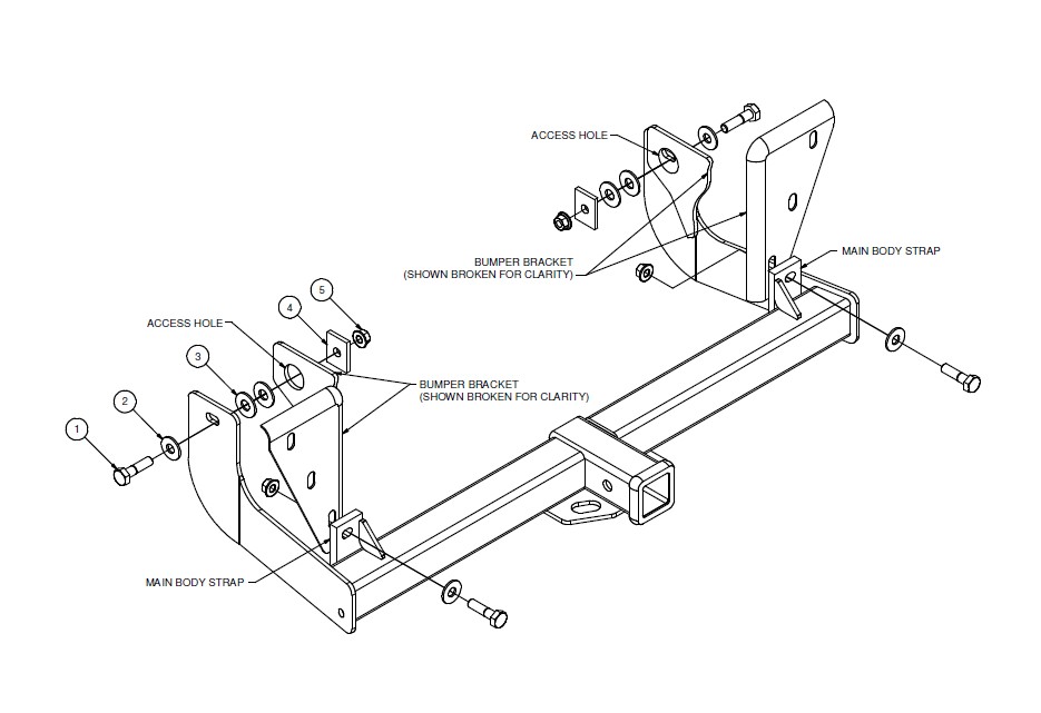
1. Raise hitch into position and fasten the hitch to the bumper brackets using the main body straps as shown.
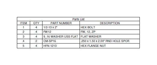
2. Attach remaining fasteners as shown, placing (2) 9/16" washers inside the access hole in the bumper bracket on each side. Use the hitch and CM-SP16 spacer to retain the washers.
3. Torque all fasteners to 110 lb-ft.
4. Reinstall spare tire if it was removed for hitch installation. Make sure the spare tire does not contact the bolts.
PERIODICALLY CHECK THIS RECEIVER HITCH TO ENSURE THAT ALL FASTENERS ARE TIGHT AND THAT ALL STRUCTURAL COMPONENTS ARE SOUND.


