FREE 1 to 3-Day Delivery on Orders $149+ Details
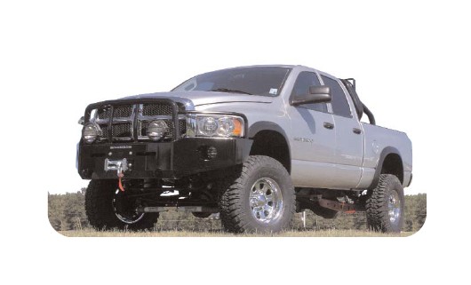
How to Install SkyJacker 4.5-5.5 in. Class I Suspension Lift Kit w/ Shocks (06-07 4WD RAM 1500) on your Dodge RAM
Tools Required
- Metric and Standard wrenches and sockets
- Assorted Drill Bits
- Floor Jack
- Jack Stands
- Measuring Tape
- Torque Wrench
- Pitman Arm Puller

Shop Parts in this Guide
IMPORTANT NOTES:
• If after installation a front driveline vibration becomes apparent, Part # IXR20K must be ordered. It is an indexing ring to rotate the transfercase down to improve driveline angle.
• Some Models will come equipped with a (larger) Sterling rear axle. These models will require a larger rear U-bolt. Order rear U-Bolt kit #U9B12R.
• Please refer to Parts List to insure that all parts and hardware are received prior to disassembly of vehicle. If any parts are found to be missing, contact your dealer as soon as possible.
• If larger tires (10% more than stock diameter) are installed, speedometer recalibration is necessary (see Dodge dealer or Tire Store).
• This lift is determined from the front while only lifting the rear to a position level with the front.
• After installation occurs, a qualified alignment facility is required to align vehicle to factory specs.
• Under NO circumstances are SKYJACKER® coil springs to be used in conjunction with any type of coil spring or spring tower block/spacer. The use of coil spring block/spacers will allow ANY coil spring to exceed its designed stress and travel loads allowing it be overstressed, oversprung, fatigued, and possibly break. SKYJACKER® warranty is void under any such application.
• For vehicles with a carrier bearing on the rear driveshaft, lowering brackets are available if a vibration occurs. 1” Drop Part # CBL3401 2 1/4” Drop Part # CBL214
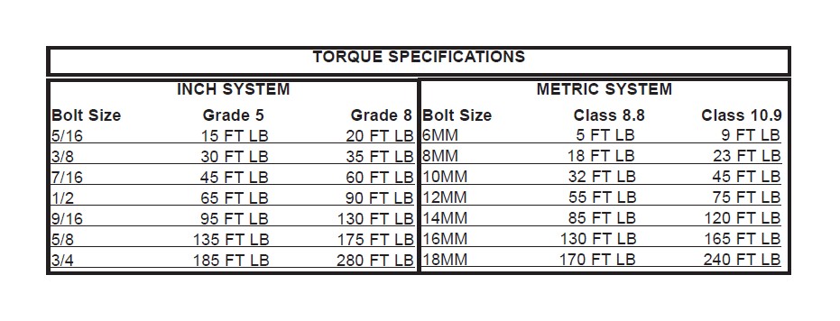
*The above specifications are not to be used when bolt is being installed with a bushing.
Installation:
1. Secure and properly block the tires of vehicle on a level concrete or asphalt surface.
2. Open hood, remove the upper shock nuts and retainers, remove the 3 nuts on the upper shock tower brackets.
3. Jack up front of vehicle and install jack stands under frame behind the lower link rear brackets. Remove tires and brakeline anchor bracket between the upper and lower links behind coil spring.
4. Loosen trackbar at the axle housing, then remove other end from the frame, and lower down.
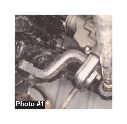
5. Remove drag link from pitman arm and lower it down, then remove pitman arm from steering sector (a puller will be required, See photo #1). Install new Skyjacker® drop pitman arm using the original lock washer and nut, and torque to OEM specs (do not reinstall drag link to pitman arm at this time).
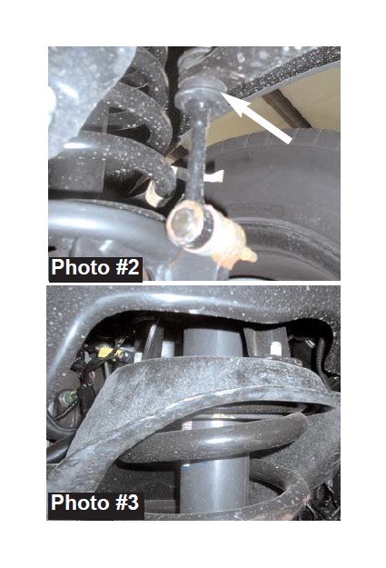
6. Loosen the front sway bar bolts at frame, but do not remove. At the differential end of the sway bar (at front of coil springs), disconnect sway bar link from the sway bar. (See Photo #2).
7. Remove upper shock tower, remove lower shock bolts and pull shocks up through the coil spring under the hood. Now lower front axle down until coil springs become loose. Remove coils, rubber insulator and 3-bolt tower ring. (See Photo #3)
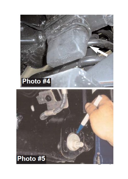
8. Locate the front rubber bumpstops, mounted on the frame rail behind the coils. Remove bumpstop from its pocket by using a large flat screwdriver to pry them out or using a pair of channel lock pliers working back and forth. (See Photo #4).
9. At the front lower link adjustment cams, mark (with an ink marker, or scribe a mark) the vertical line on the cam and the reinforcement bracket for reference so you can realign the marks after installation. (See Photo #5.)
10. Install drive-in zirk fittings in each end of all 4 links by using a 1/4" socket over the fitting, tap with a hammer until fitting is completely tapped in.
11. Install poly bushings in each end: #2617 in the lower/larger links, #2618 in the upper/smaller links. Be sure to slightly grease them prior to installation. Insert the steel sleeve tube in the links: 2.645" long sleeve in the lower/larger links, 2.375" long sleeve in the upper/smaller links.
12. Loosen and remove the upper and lower links from both sides. Now replace the lower links with new Skyjacker® links (one side at a time). Only start these bolts, do not tighten at this time. NOTE: so that the links may be greased while on the vehicle, install the lower links with the zirk fittings positioned as follows: front eye of link has fitting pointing out the end, rear eye of link should have the fitting pointing down.
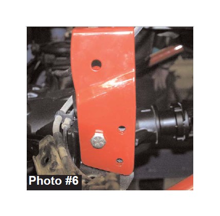
13. Install new upper control arm relocation bracket over the factory bracket on the axle. Install the 9/16 x 5” fine thread bolt with washers and nuts into the factory mounting hole. Be sure to install the 2.375” crush sleeve on this bolt inside of the factory bracket. (See Photo #6)
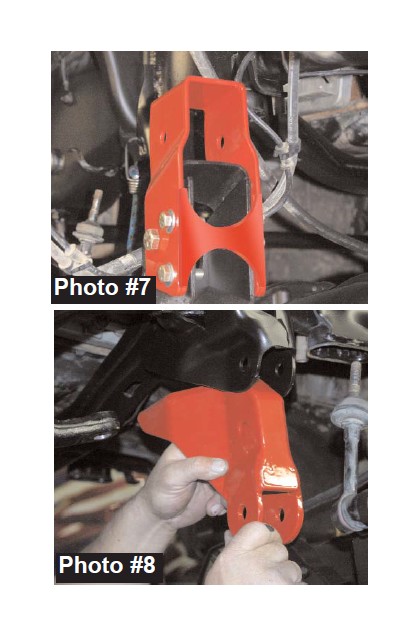
14. Mark the two additional holes on each side of bracket and drill using 15/32” drill bit. Once drilled, install the 7/16 x 1 1/2” fine thread bolts, washers, and nuts. If installing Skyjacker Dual Shock Kit, be sure to install bottom dual shock bracket at this time.(See Photo #7).
15. Now when installing the new upper Skyjacker® links slide the front eye through the new upper relocation bracket enough to bolt the rear eye in the original frame mount. Then position and bolt front eye through upper relocation bracket using original bolt and nut. Only start these bolts, do not tighten at this time. NOTE: So that the links may be greased while on the vehicle, install the upper links with the zirk fittings positioned as follows: front eye of link has fitting pointing out the end, rear eye of link should have the fitting pointing up.
16. Install new track bar drop bracket into the factory mount. (See Photo #8). Attach to the OEM mounting hole using the factory bolt and hardware.
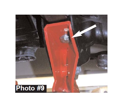
17. Install the 1/2 x 4 1/2” fine thread bolt, washers, and nut into the bottom of the bracket up thought the factory mount. (See Photo #9.)
18.To begin coil spring installation, insert original 3-bolt tower ring in place inside top of coil tower, and start a couple of the nuts to hold ring in place (do not tighten). NOTE: If installing dual shock kit, it is important to see those instructions at this time.
17.Start coil springs at bottom, place rubber isolator on top of coil and then start coil into position in the upper tower, on both sides. Align coil springs so that the end of the bottom wraps are turned to the inside at the center of the axle. Lift up on jack under differential until coil springs are securely in place, and keep a load on them to hold in place.
18.Now remove nuts that were put on 3-bolt tower ring in step 16. Install new shocks down through coil towers under hood and install lower bolts. Place a retainer and poly bushing on shock stems. Now install original upper shock bracket over 3 bolts of tower ring, install 7/16" self locking nuts and tighten. Install shock grommets, retainer washers and nuts. Tighten nuts. NOTE: If installing dual shock kit, included in the Class 2 suspensions, it is important to see those instructions at this time.
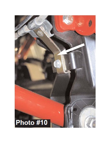
19. Attach new front brake line relocation bracket to the factory position using the factory bolt. Attach brakeline to new relocation bracket using the 5/16 x 1” fine thread bolt, washer, and nut. Use the washer under the nut. (See Photo #10)
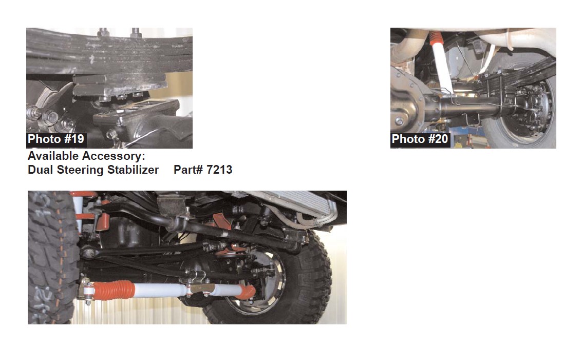
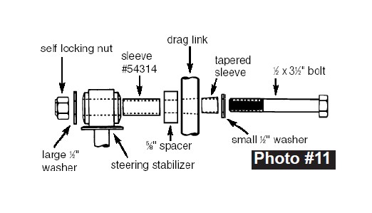
20. Remove OEM steering stabilizer from drag link and axle. To install new Steering Stabilizer: insert a poly bushing and steel sleeve #54314 into the piston end of the stabilizer. Insert poly bushing and the shorter sleeve into the body end of stabilizer. Attach red boot and secure with tie strap. To install piston end of stabilizer to the drag link use the hardware shown in photo #11: insert tapered sleeve into tapered hole in the tie rod, place the small 1/2" washer on the new 12 x 5" bolt and install through drag link hole. Install the 5/8" spacer, the piston end of steering stabilizer (with sleeve #54314 sleeve in the eye), large 1/2" washer, and 1/2" self locking nut onto bolt, and tighten. Attach the body end of the stabilizer into the factory mount using factory bolt and hardware.
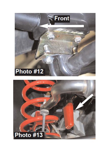
21.Take the stud ends of the front sway bar and swing them back up and reattach. Now remove the 2 bolts at the frame from each side of sway bar and lower bar down. Install new sway bar lowering brackets with the offset sloping toward the front bumper (See Photo #12) using OEM hardware at top and the 7/16 x 1 1/2” fine threadbolts, washers, and nuts at bottom.
22. Install tires, remove jack stands, and lower vehicle to the ground. Attach drag link to pitman arm, torque to OEM specs.
23. Place the new poly bumpstops in the original bumpstop pocket. By using leverage against the bottom of bumpstop, force the bumpstop into place. (See Photo #13).
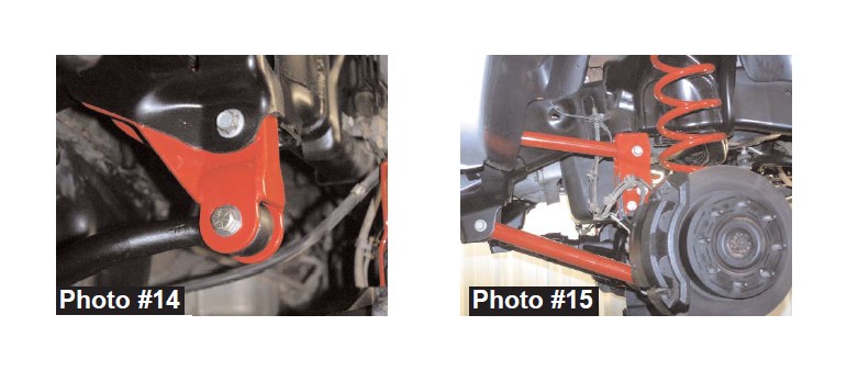
24. Raise the track bar up and bolt to the bottom of the new track bar drop bracket using the 9/16 x 3” fine thread bolt, washers, and nut. (See Photo #14). (It may be necessary to turn steering wheel left or right in order to realign holes when installing bolt.) Tighten to OEM specs. Now retighten the track bar bolt on the passenger side axle housing.
25. Tighten each end of the upper and lower links being sure to realign the marks on the eccentric cams. (See Photo #15). Thoroughly grease all 8 zirk fittings. After the lift is complete take vehicle to a qualified alignment shop so that caster, toe-in, toe-out and steering wheel alignment can be checked.
26. Install polyurethane bushings and steel sleeves in bottom eyes of front shocks (the front shocks are those with a "stud" top and "eye" bottom), and place a washer and stem bushing on the upper studs of the shocks. From under the hood, lower shocks down through the coil spring, install and tighten bottom bolts. Remove the nuts on the coil spring's 3-bolt tower ring installed previously. Now place the original shock tower (that was removed earlier in step 7, over the shock's stud and align over the threads of the 3-bolt tower ring. Install and tighten self locking nuts on both tower rings. Install upper shock stem bushings, washers, washer and nuts. Tighten nuts. NOTE: If installing dual shock kit, it is important to see those instructions at this time.
WARNING: On the Dodge Ram trucks, the front shock absorbers limit extended position of the front suspension! The use of shocks other than those specified by Skyjacker®, may cause coil disengagement, adverse steering angles, brakehose failure, driveline component failure, and/or other related component failure! The use of other shocks will void your Skyjacker® warranty!
29.Cycle the steering to full left and right turns checking clearance between the sway bar end links mounts, at front base of coil springs, and the drag link tie rod assembly.
REAR:
30. Place a floor jack under rear axle and raise vehicle. Place jack stands under the frame to support vehicle and remove the rear tires and shock absorbers.
31. Remove the axle U-bolts and lower axle down a few inches. Care should be take because when U-bolts are removed, axle can move freely.
IF INSTALLING A SOFTRIDE® “SYSTEM” WITH NEW REAR SPRINGS, SKIP TO STEP #36.
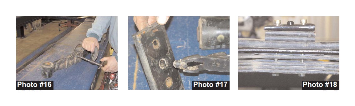
32. ADD-A-LEAF INSTALLATION: To perform the installation of add-a-leafs properly you must use two large C-clamps to contain the elastic potential energy in a leaf spring when the center tie bolts are being removed. Attach and tighten a C-clamp on each end of the leaf spring to hold spring assembly securely together. (See Photo #16) Using vise-grips to hold the head of the two outer center bolts, loosen and remove them. With care, slowly loosen and remove the C-clamps.
33. With Tie bolts removed, remove the plastic dial pin from the bottom shim plate. (See Photo #17.) The New Skyjacker Degree Shim is produced with a dial pin built in.
34. Insert new tie bolts through new axle wedge shim (thick end towards rear bumper), 2 bottom OEM shim plates, original bottom overload leaf, new add-a-leaf, and through original spring pack. Only finger tighten the nut. (See Photo #18)
35. DO NOT USE THE CENTER TIE BOLTS TO DRAW THE SPRING LEAVES TOGETHER. FAILURE OF ANY COMPONENT CAN CAUSE AN EXPLOSIVE DISASSEMBLY AND POSSIBLE INJURY! Place one C-clamp on each side of the center bolts and tighten evenly. Once C-clamps have drawn leaves securely together, hold the center tie bolt heads with vise-grips and torque nuts to 41 Ft. Lbs. Remove C-clamps. Cut off excess length of tie bolts. Skip to step 38.
36. NEW SPRING INSTALLATION: Safely support fuel tank. Loosen vent and fill hoses on filler neck. Loosen, do not remove, the front fuel tank strap bolt. Disconnect and remove the rear bolt and strap. Carefully slide fuel tank toward center of vehicle to acquire sufficient room to access the driver side front spring eye bolt.Remove the spring eye bolts and remove original springs from vehicle. It will be necessary on the driver side, to pry the gas tank away from frame allowing more room to remove and reinstall factory bolt. NOTE: do not pry gas tank too much or lower down too much because the fitting at top may be broken off.
37. Install new springs with thick end of bottom wedge shims towards the rear bumper. Reconnect rear fuel tank strap and bolt, tighten front strap bolt, and tighten vent and fill hoses on filler neck.
38. Raise the rear axle back up, aligning spring pins into axle housing. (See Photo #19.) Install and tighten new u-bolts evenly (torque u-bolts to 85-90 ft.lbs.)
39. Install rear shock absorbers, tires, remove jack stands and lower vehicle down. (See Photo #20).
FINAL NOTES:
* After installation is complete, double check that all nuts and bolts are tight.
* Rotate driveshafts and check for interference at differential yoke and cardan joint. If necessary, lightly dress casting(s) and/or U-joint tabs in order to eliminate binding.
* Check to ensure there is adequate clearance between All rotating, mobile and fixed members. Check clearance between inner side wall of tires. It may be necessary to reset steering stops to eliminate interference.
* Ensure there is adequate clearance between exhaust and brakelines, fuel lines, fuel tank, floor board, and wiring harnesses. Check steering gear for interference and proper working order. Inspect brakelines for damage and adequate clearance. Test brake system.
* With the vehicle on the floor, cycle steering lock to lock and inspect steering, suspension, driveline and brakeline systems for proper operation, tightness and adequate clearance.
* Have headlights readjusted to proper settings.
* Front end realignment is necessary so have a qualified alignment center realign front end to factory specifications.