FREE 1 to 3-Day Delivery on Orders $149+ Details
How to Install Rough Country 5 in. Suspension Lift Kit on your Ram
Installation Time
6 hours
Tools Required
- Torsion Bar Adjuster Tool
- 1/2” Ratchet
- Ball Hammer
- Pry Bar
- 4” 1/2” Socket Extension
- T-60 Torx Socket
- Torque Wrench
- T-30 Torx Socket
- 26mm Socket
- 13mm Socket
- 16mm Socket
- Cutting Wheel
- Thread Locker
- 7/32 Allen Wrench
- Floor Jack
- 19mm Socket
- 15mm Socket
- 24mm Deep Socket
- 19mm Deep Socket
- 21mm Wrench
- Tape Measure
- 2 Jack Stands
- 14mm Socket
- 24mm socket

Shop Parts in this Guide
Front Installation
1. The tools needed for this installation are on the front cover. A list of all the parts in this kit are under the tool listing. Make sure you have all of the proper tools and a understanding of these directions before you proceed.
2. Place the truck on a clean level surface and set the parking brake. Chock the rear wheels and using a floor jack raise the front of the truck and support the frame rails with approved jack stands. Remove the front wheels. NEVER WORK UNDER AN UNSUPPORTRD VEHICLE
3. Measure the threads showing on the torsion bar adjuster bolt. See Photo 1. Mark the torsion bars on the AArm and Torsion bar key. Mark the drivers side and passenger side. See Photo 2.
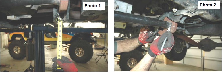
4. Using a torsion bar tool relieve the pressure from the torsion bar adjuster bolt and remove the bolt and swivel nut.
5. Remove the torsion bars from the vehicle.
6. If equipped remove the factory skid plate.
7. Starting on the drivers side of the truck use a 16mm deep well sock remove the sway bar bushings from the top of the sway bar and remove the sway bar link from the lower control arm using a 15mm wrench.
8. Using a 13 mm socket remove the caliper and secure it to the frame rail. Do not let the caliper hang from the brake line.
9. Using a 18mm socket remove the caliper hold down bracket and set aside.
10. Using a 36 mm socket remove the CV shaft nut and set aside.
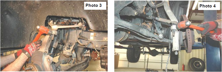
11. Using a 21 mm deep well socket loosen the upper ball joint nut. Using a hammer hit the knuckle as shown in Photo 3 until the ball joint breaks free. NEVER HIT THE BALL JOINT THREADS OR THE BALL JOINT.
12. Using a 21 mm deep well socket remove the tie rod end nut. Using the hammer hit the knuckle as shown in Photo 4 until the tie rod pops out. NEVER HIT THE TIE ROD THREADS OR THE TIE ROD.
13. Using a 24 mm deep well socket remove the lower ball joint nut. Using a hammer hit the knuckle until the ball joint pops out. NEVER HIT THE BALL JOINTTHREADS OR THE BALL JONT.
14. Remove the upper ball joint nut and set the knuckle aside.
15. Using a T60 Torx bit and 24 mm deep well socket remove the rear lower back control arm. Using a 24 mm deep well socket and 24 mm wrench remove the lower control arm bolt.
16. Set the lower control arm aside.
17. Repeat steps 7 through 17 on the passengers side.
18. Remove the cross member that connects the rear frame brackets of the lower control arms. The four bolts will be reused.
19. Using the bolts just removed, install the rear cross member with the ears of the kickers facing to the back of the truck.
20. Using Bag 4 install the front cross member, do not tighten at this time
21. Using factory hardware install both of the lower control arms.
22. Support the front differential. Remove the drivers side rear mounting bolts, front drivers side bolts, and the passenger side bolts. Lower the differential about 4 inches.
23. Using Bag 1 install the drop brackets on the drivers side front as shown in Photo 5 & 6. Do not tighten at this time.
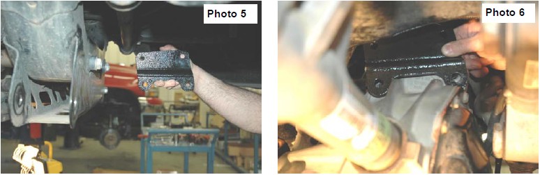
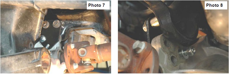
24. Install the drivers side rear bracket and spacers as shown in Photo 7 & 8. Do not tighten at this time. See Below.
25. Using bag 3 install the passengers side drop brackets as shown in Photo 9. The angle of the brackets must match at the top and fit on the differential as shown in Photo 10.
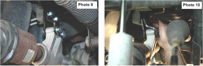
26. Before tightening the bolts slightly shake the differential. Starting on the passengers side bracket torque all the bolts to 70 ft lbs.
27. On some Hemi models if interference occurs between the exhaust pipe and the drive shaft, the exhaust pipe may need to be reshaped or rerouted. The pipe may be very slightly reshaped using a ball hammer although professional exhaust modification is recommended to clear the driveshaft.
28. One side at a time remove the dust shield, wheel bearing assembly, and ABS bracket from the stock knuckles. Install them on the new knuckles and torque to 120 ft lbs.
29. Support the lower control arm with a jack, install the CV spline into the knuckle and install the knuckle on the lower control arm. Lift the knuckle upwards and install the upper control arm on the knuckle. Lower ball joint and torque to 60 ft lbs, upper ball joint to 50 ft lbs, and CV shaft to 170 ft lbs.
30. Install the tie rod into the knuckle and torque to 50 ft lbs.
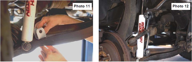
31. Install the supplied sway bar bracket on the lower control arm with the supplied 12mm x 35mm bolts. Tighten using a 18mm & 19mm wrench. See Photo 11.
32. Install the sway bar bracket to the sway bar using supplied hardware. Turn the upper bracket 90 degrees from the lower bracket. Tighten lower using an 18mm & 19mm wrench using supplied 12mm x 65mm bolts and flange nuts. See Photo 12.
33. Remove the rubber bump stop from the bump stop cup and remove the mounting cup from the frame using a cutting wheel as shown in Photo 13. Reinstall the factory bump stop cup on the bump-stop spacer bracket as shown in Photo 14 with the supplied 3/8” x 1 1/4” bolts, washers & flange lock nuts.
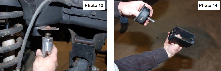
34. Mount the assembly in the factory location on the frame using the supplied 3/8” x 1 1/4” bolts, washers/nuts. Reinstall the factory rubber bump stop in the cup.
35. Install the front shock with the factory hardware
36. Install the rear stinger brackets on to the stock frame cross member using the stock hardware. Turn the bolt around as shown to clear the stinger.
37. Install the supplied front stinger brackets to the new cross member with the supplied 1/2” x 2 1/2” bolts & nuts. Tighten hardware.
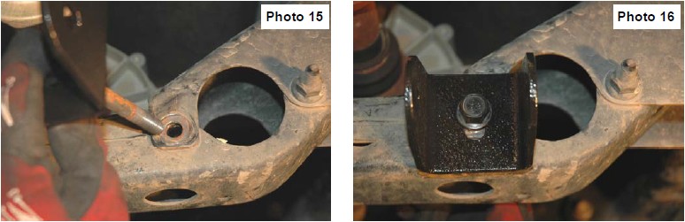
38. Install the stingers using the bolts in Bag 5. Do not tighten at this time. See Photo 15 & 16.
39. Place the rotor on the knuckle, install brake pads, and caliper hold down, and caliper.
40. Install the new skid plate and tighten to 35 ft lbs. If the upgraded front skid plate was purchased install this with the lower skid plate.
41. Tighten the front cross member to 130 ft lbs, the rear to 70 ft. lbs, stinger brackets to 70 ft lbs, and stingers to 70 ft. lbs.
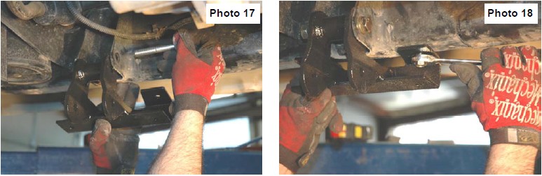
42. Remove the two bolts that hold the torsion bar cross member and remove. Install the cross member drop bracket using the stock bolts. See Photo 17. Using a ratchet install the four self tapping bolts as shown in Photo 18 from Bag 6 through the drop bracket and onto the frame. Install the torsion bar cross member using the bolts from Bag 6. Torque the upper and lower bracket bolts to 55 ft lbs.
43. Install the torsion bars into the lower control arms and back into the cross member aligning the marks made during disassembly.
44. Using the torsion bar tool apply pressure to the torsion key until the swivel nut can be inserted. Install the torsion adjusters and set them to the same amount of thread showing before disassembly.
45. If the truck has the Off Road package skid plate install it reusing the factory bolts. The 2005 skid plate can not be used.
46. Install the wheels, raise the truck, remove the jack stands, and lower to the ground.
Rear Installation
1. Chock the front wheels, raise the rear of the truck, support the frame rails, with approved jack stands, and remove the wheels.
2. Remove the factory shocks.
3. Support he axle with a floor jack. Using a 22 mm remove the u-bolts. Lower the axle about 4 inches.
4. Install the lifted block with the taper facing to the front of the truck and center pin facing down into the axle. Raise the axle until the center pin goes into the block. Install the new u-bolts and torque to 110 ft lbs. The ubolts must have an even number of threads showing.
5. Install the new rear shock with supplied hardware.
6. Install the wheels. Raise the truck remove the jack stands, and lower the truck to the ground.
7. Torque all lug nuts to 140 ft lbs.
8. Vehicle will need an alignment. Recommended specs caster 4.4deg /- 1 deg., camber 0 deg. to -.3 deg, Toe .1 /-.1 deg.
Post Instructions
1. Turn the wheels fully to the right and left to insure all components clear and do not interfere. Inspect for tire, wheel, and brake hose clearance.
2. Inspect steering and suspension for tightness and proper operation .
3. The headlights will need to be adjusted to compensate for the lift.
4. It is the ultimate buyers responsibility to have all bolts and nuts checked for tightness after the first 500 miles and then every 1000 miles. Wheel alignment steering system, suspension and driveline systems must be inspected by a qualified professional mechanic at least every 3000 miles.
KIT COMPONENTS
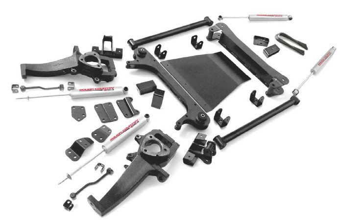
Kit Contents
Driver & Passenger Knuckles
Torsion Bar Drop Bracket (2)
Bump Stop Extensions Brackets (2)
Sway Bar Links (2)
Differential Drop Bracket Pass/Side
Differential Drop Bracket Drivers/Front
Differential Drop Bracket Drivers/Rear
Kicker Braces (2)
Kicker Brace Brackets (4)
Front Shock 658699
Front/ Rear Cross Member
Cross Member Skid Plate
Hardware Bags
Lift Blocks (2) and U-Bolts (4)
Rear Shock 658694