FREE 1 to 3-Day Delivery on Orders $149+ Details
How to Install K&N Series 77 High Flow Performance Cold Air Intake on your Ram
Installation Time
1 hours
Tools Required
- Flat Blade Screwdriver
- Ratchet
- 8mm Socket
- 10mm Socket
- 13mm Socket

Shop Parts in this Guide
NOTE: FAILURE TO FOLLOW INSTALLATION INSTRUCTIONS AND NOT USING THE PROVIDED HARDWARE MAY DAMAGE THE INTAKE TUBE, THROTTLE BODY AND ENGINE.
TO START:
1. Turn off the ignition and disconnect the negative battery cable.
NOTE: Disconnecting the negative battery cable erases pre-programmed electronic memories. Write down all memory settings before disconnecting the negative battery cable. Some radios will require an anti-theft coded to be entered after the battery is reconnected. The anti-theft code is typically supplied with your owner’s manual. In the event your vehicles’ anti-theft code cannot be recovered, contact an authorized dealership to obtain your vehicles anti-theft code.
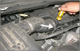
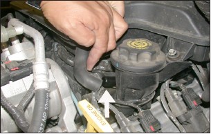
2. Loosen the hose clamp at the intake resonator as shown.
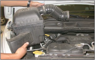
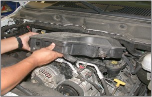
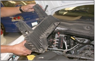
3. Disconnect the intake tube, then, pull firmly upwards to remove the air cleaner assembly as shown.
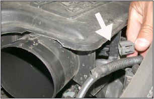
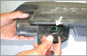
4. Disconnect the air temperature sensor electrical connection as shown.
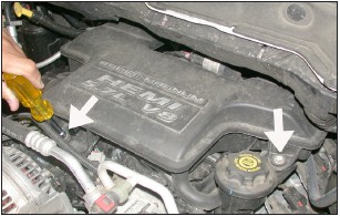
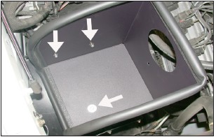
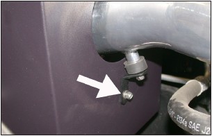
5. Loosen the two bolts that secure the intake resonator to the manifold as shown.
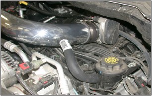
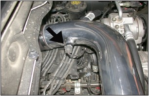
6. Disconnect the crankcase vent hose as shown.
7. Pull firmly upwards to remove the air intake resonator as shown.
NOTE: K&N Engineering, Inc., recommends that customers do not discard factory air intake.
8. Turn the air temperature sensor 1/4 turn, then, remove the air temperature sensor from the air intake resonator as shown.
NOTE: The air temperature sensor is frail in construction so take care when removing from the sensor from the resonator.
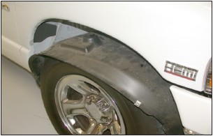
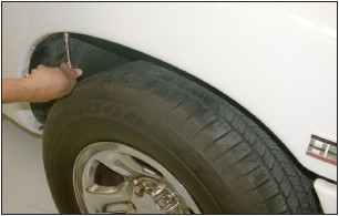
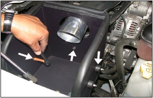
9. Loosen and remove the 8 bolts that secure the inner fender valance, then, lower the valance down as shown.
10. Remove the air cleaner support bracket which is held in place by four bolts.
11. Reinstall the inner fender valance using 6 of the original 8 bolts removed in step 9.
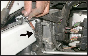
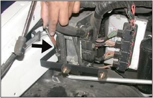
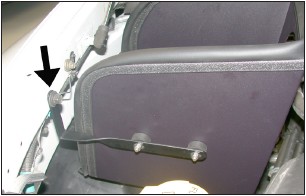
12. Remove the screw that secures the computer to the inner fender as shown.
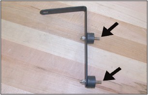
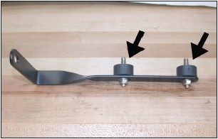
13. Install the rubber mounted studs onto the “L” bracket using the provided hardware but do not completely tighten at this time.
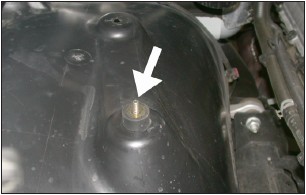
14. Secure the “L” bracket assembly to the threaded hole from step 12 using the original bolt as shown.
15. Secure the provided rubber mounted stud to the hole on the plastic inner fender valance using the provided hardware, but do not completely tighten at this time.
16. Install the provided rubber mounted studs onto the twist bracket as shown using the provided hardware, but do not tighten completely at this time.
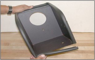
17. Install the provided edge trim onto the heat shield as shown.
18. Install the twist bracket onto the heat shield and secure with the provided hardware as shown, but do not tighten completely at this time.

19. Using the provided hardware install and secure the heat shield to the rubber mounted studs on the “L” bracket and on the inner fender as shown.
20. Secure the twist bracket to the threaded hole on the inner fender using the original hex bolt from step 10.
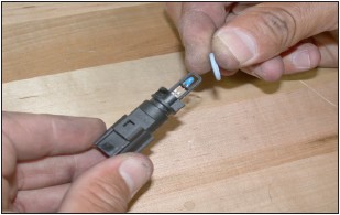
21. Remove the o-ring from the stock air temperature sensor as shown.
NOTE: Be careful not to damage the o-ring.
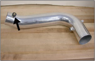
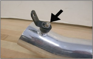
22. Install the rubber mounted stud into the threaded boss on the K&N® intake tube as shown.
23. Install the angled bracket onto the rubber mounted stud using the provided hardware as shown, but do not tighten completely at this time.
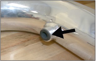
24. Install the provided silicone hose into the vent on the K&N® intake tube as shown.
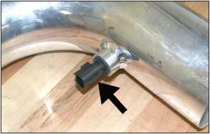
25. Slide the air temperature sensor into the silicone hose as shown.
NOTE: The plastic cage on the end of the air temperature sensor is very fragile so take care when installing the air temperature sensor into the silicone hose.
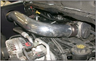
26. Slide the intake tube into the heat shield then slide the tube into the silicone hose on the throttle body as shown, but do not tighten completely at this time.
27. Secure the angle bracket to the heat shield using the provided hardware as shown, but do not tighten completely at this time.
28. Adjust everything for best fit and clearance then tighten all hardware as shown.
29. Attach the provided 5/8”id crank case vent hose onto the appropriate fitting on the K&N® intake tube, trim for proper fitment to prevent the hose from developing a kink and attach the open end to the crank case vent port.
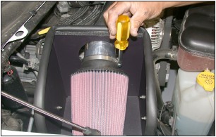
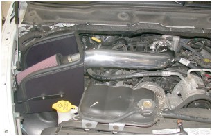
30. Install the K&N® air filter onto the intake tube and secure with the provided hose clamp as shown.
NOTE: Drycharger® air filter wrap; part # RC-3690DK is available to purchase separately. To learn more about Drycharger® filter wraps or look up color availability please visit http://www.knfilters.com.
31. Reconnect the air temperature sensor electrical connection as shown.
NOTE: Due to manufacturer’s tolerance, the temperature sensor pig tail wiring may need to be un-taped from the main wiring harness to gain sufficient wiring length.
32. Reconnect the vehicle’s negative battery cable. Double check to make sure everything is tight and properly positioned before starting the vehicle.
33 The C.A.R.B. exemption sticker, (attached), must be visible under the hood so that an emissions inspector can see it when the vehicle is required to be tested for emissions. California requires testing every two years, other states may vary.
34. It will be necessary for all K&N® high flow intake systems to be checked periodically for realignment, clearance and tightening of all connections. Failure to follow the above instructions or proper maintenance may void warranty.
ROAD TESTING:
1. Start the engine with the transmission in neutral or park, and the parking brake engaged. Listen for air leaks or odd noises. For air leaks secure hoses and connections. For odd noises, find cause and repair before proceeding. This kit will function identically to the factory system except for being louder and much more responsive.
2. Test drive the vehicle. Listen for odd noises or rattles and fix as necessary.
3. If road test is fine, you can now enjoy the added power and performance from your kit.
4. K&N Engineering, Inc., suggests checking the air filter element periodically for excessive dirt build-up. When the element becomes covered in dirt (or once a year), service it according to the instructions on the Recharger® service kit, part number 99-5050 or 99-5000.