FREE 1 to 3-Day Delivery on Orders $149+ Details
How to Install K&N Series 57 FIPK Cold Air Intake on your Ram
Installation Time
1 hours
Tools Required
- 6” Extension
- 7/8” Drill Bit
- 7/16” Socket
- 7/16” Wrench
- 8mm Deep Socket
- 10mm Socket
- 13mm Socket
- Drill
- Flat Blade Screwdriver
- Ratchet

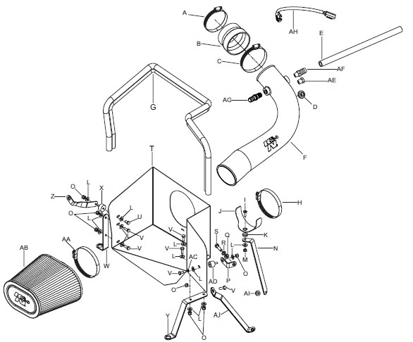
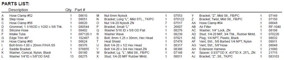
Shop Parts in this Guide
NOTE: FAILURE TO FOLLOW INSTALLATION INSTRUCTIONS AND NOT USING THE PROVIDED HARDWARE MAY DAMAGE THE INTAKE TUBE, THROTTLE BODY AND ENGINE.
TO START:
1. Turn off the ignition and disconnect the negative battery cable.
NOTE: Disconnecting the negative battery cable erases pre-programmed electronic memories. Write down all memory settings before disconnecting the negative battery cable. Some radios will require an anti-theft code to be entered after the battery is reconnected. The anti-theft code is typically supplied with your owner’s manual. In the event your vehicles’ anti-theft code cannot be recovered, contact an authorized dealership to obtain your vehicles anti-theft code.
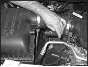
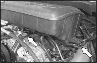
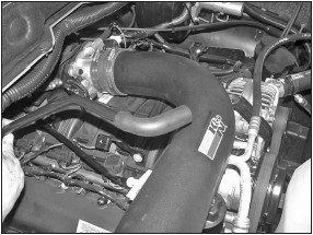
2. Loosen the hose clamp that connects the intake tube to the resonator box then remove the intake tube.
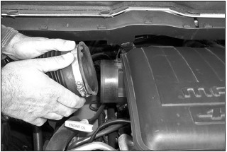
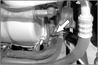
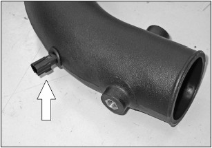
2a. On 2008 and later model year vehicles, disconnect the crank case vent hose from the air box as shown.
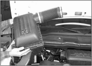
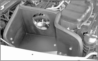
3. Lift up firmly to release the air box from mounting studs, then remove completely.
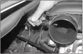
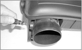
4. On models that come equipped with air temp sensors, unplug the air temp. sensor electrical connection as shown.
NOTE: On some models the air temperature sensor may be in the front of the resonator chamber.
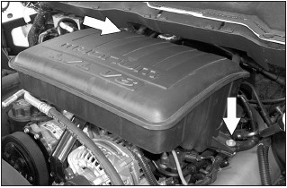
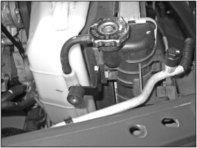
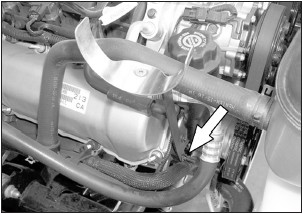
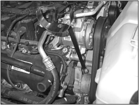
5. Remove the two 10mm bolts that retain the resonator box onto the engine.
NOTE: On 2008 and later model year vehicles there will be only one bolt to secure the resonator.
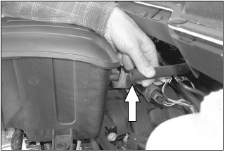
6. Pull up firmly to release the resonator from engine.
7. On 2002-2007 model year vehicles, disconnect the crank case vent hose from resonator box as shown. Then remove resonator box from vehicle. NOTE: K&N Engineering, Inc., recommends that customers do not discard factory air intake.
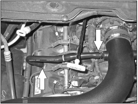
8. On 2002-2007 model year vehicles, loosen hose clamp that retains the rubber hose to the throttle body then remove as shown.
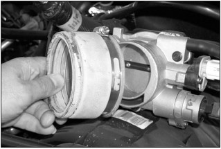
8a. Install the provided silicone hose (08051) onto the throttle body and secure with the provided hose clamp.
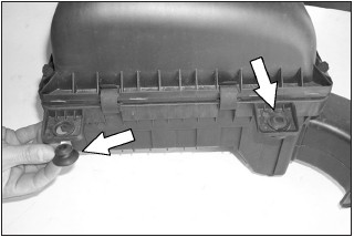
9. Remove the two rubber bushings from the factory air box as shown.
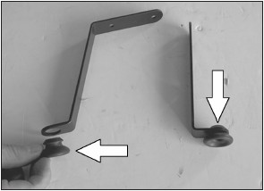
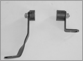
10. Install the two rubber bushings that were removed in the previous step into the provided brackets as shown.
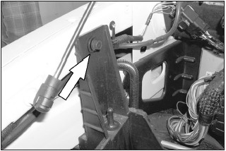
11. Install the large “Z” bracket onto the heat shield with the provided hardware. Do not tighten completely at this time.
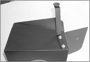
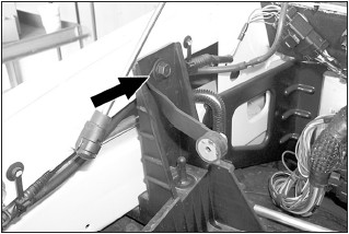
12. Install the “L” bracket onto the heat shield with the provided hardware. Do not tighten completely at this time.
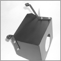
13. Install the rubber mounted studs into the provided brackets as shown
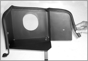
14. Install the provided edge trim onto the heat shield. Trim if necessary.
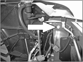
15. On 2008 & earlier vehicles, remove the 13mm bolt from the upper fan shroud as shown.
16. On 2008 & earlier vehicles install the “L” bracket (26607) onto the fan shroud with the provided 8mm bolt and washers.
17. On 2009 and later model vehicles, remove the bolt shown from the radiator core support.
17a. On 2009 and later model vehicles, install the provided heat shield mounting bracket onto the radiator core support using the bolt removed in the previous step.
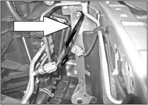
18. Remove the 8mm bolt that retains the air box mount.
18a. Install the twisted ”L” bracket with the bolt that was removed in step 18. Do not tighten bolt completely.
19. Assemble the saddle bracket assembly as shown.
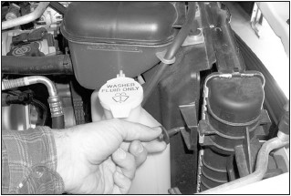
20. On 2002-2007 model year vehicles, use a 8mm socket, remove the stud that retains the oil fill bracket.
21. On 2002-2007 model year vehicles, install the saddle bracket assembly with the stud that was removed in step 20.
21a. On 2008 and later model year vehicles, remove the lower A/C bracket mounting bolt shown.
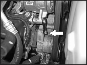
21b. On 2008 and later model year vehicles, install the tube mounting bracket using the bolt removed in the previous step and the spacer provided.
22. Install the heat shield onto the factory air box studs then mount to the previously installed brackets.
23. On models that come equipped with temp sensors, remove the air temp sensor from the resonator box as shown.
NOTE: Take care removing the temp sensor as it is very fragile.
NOTE: On 2008 and later models the air temperature sensor is located on the front of the resonator.
24. On models that come equipped with temp sensors, drill a 7/8” hole in the K&N® intake tube at the drill point.

25. Install the provided grommet into the K&N® intake tube as shown.
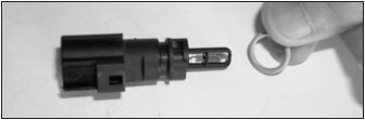
26. Remove the O-ring from the air temp. sensor as shown.
NOTE: Take care when handling the temp sensor as it is very fragile.
27. Install the air temp sensor into the K&N® intake tube as shown.
NOTE: Take care when handling the temp sensor as it is very fragile.
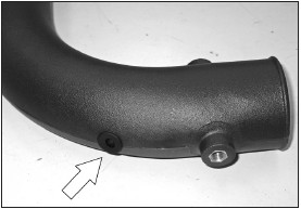
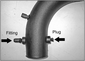
27a. On 2002-2007 model year vehicles, install the NPT fitting and NPT plug as shown.
NOTE: Plastic NPT fittings are easy to cross thread. Install the vent fitting “hand” tight, then turn it two complete turns with a wrench.
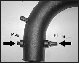
27b. On 2008 and later model year vehicles, install the NPT fitting and NPT plug as shown.
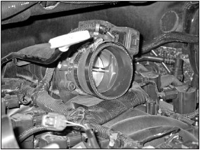
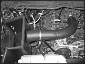
28. Install the K&N® intake tube into the silicone hose at the throttle body and align to the mounting bracket, secure the intake tube with the hose clamps provided.
29. On models equipped with an air temperature sensor, connect the harness extension into the factory connector and then connect the open end onto the air temperature sensor.
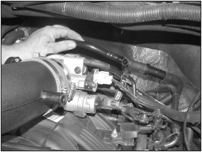
30. On models that the crank case vent hose is connected to the “T” on the drivers side of the engine, remove the factory vent hose from the “T” fitting as shown.
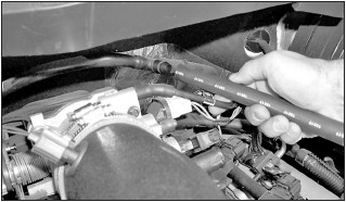
30a. On models that the crank case vent hose is connected to the “T” on the passengers side of the engine, remove the complete vent tube assembly from the rubber fittings in each valve cover as shown.
30b. On models that the crank case vent hose is connected to the passenger side valve cover, remove the factory 90° coupling hose from the plastic vent tube.
NOTE: On 2008 and later model year vehicles, disconnect the crank case vent hose directly from the valve cover.
30c. Cut the crank case vent tube 1” from the “T” fitting as shown.
NOTE: Cut the tube that was originally fastened to the air box.
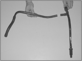
30d. Rotate the long side of the vent tube assembly 180° as shown.
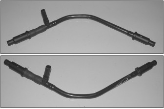
30e. Reinstall the vent tube assembly into the rubber fittings in each valve cover so that the “T” fitting is now on the drivers side of the engine facing forward.
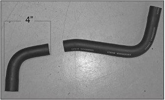
30f. On 2008 and later model year vehicles, cut the factory crank case vent hose 4” from the end as shown.
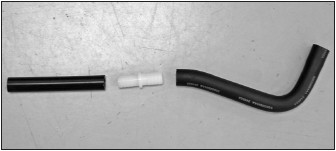
30g. On 2008 and later model year vehicles, insert the provided hose mender into the remaining piece of the factor vent hose and then cut the provided vent hose to 5” length connect onto the hose mender.
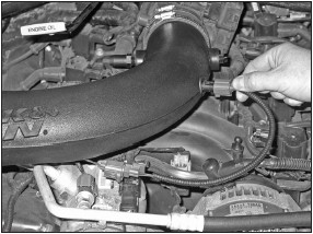
31. Connect the provided vent hose onto the “T” fitting then connect the other end onto the intake tube.
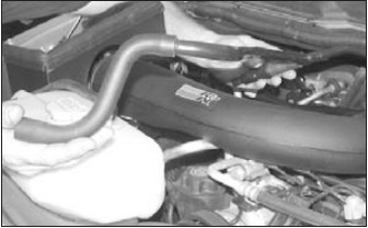
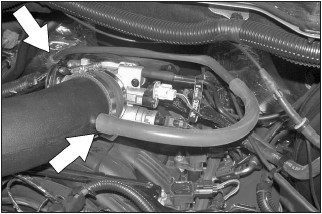
32. On models with the crank case vent tube connected to the passenger side valve cover, connect the provided silicone hose onto the factory vent tube and then route the crank case tube assembly behind the throttle body as shown and connect the open end onto the K&N® intake tube.
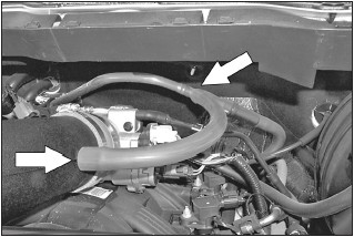
33. On 2008 and later model year vehicles, connect the crank case vent hose assembly to the valve cover port and intake tube vent fitting as shown.
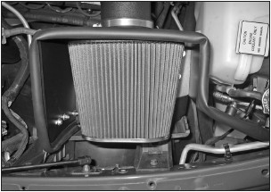
34. Install the K&N® air filter onto the intake tube as shown.
NOTE: Drycharger® air filter wrap; part # RF-1040DK is available to purchase separately. To learn more about Drycharger® filter wraps or look up color availability please visit http://www.knfilters.com®.
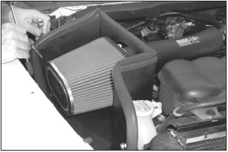
35. Align the heat shield for best clearance then tighten all the brackets.
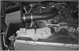
36. Reconnect the vehicle’s negative battery cable. Double check to make sure everything is tight and properly positioned before starting the vehicle.
37. The C.A.R.B. exemption sticker, (attached), must be visible under the hood, so the emissions inspector can see it when the vehicle is required to be tested for emissions. California requires testing every two years, other states may vary.
38. It will be necessary for all K&N® high flow intake systems to be checked periodically for realignment, clearance and tightening of all connections. Failure to follow the above instructions or proper maintenance may void warranty.
ROAD TESTING:
1. Start the engine with the transmission in neutral or park, and the parking brake engaged. Listen for air leaks or odd noises. For air leaks secure hoses and connections. For odd noises, find cause and repair before proceeding. This kit will function identically to the factory system except for being louder and much more responsive.
2. Test drive the vehicle. Listen for odd noises or rattles and fix as necessary.
3. If road test is fine, you can now enjoy the added power and performance from your kit.
4. K&N Engineering, Inc., requires cleaning the intake system’s air filter element every 100,000 miles. When used in dusty or off-road environments, our filters will require cleaning more often. We recommend that you visually inspect your filter once every 25,000 miles to determine if the screen is still visible. When the screen is no longer visible some place on the filter element, it is time to clean it. To clean and re-oil, purchase our filter Recharger® service kit, part number 99-5050 or 99-5000 and follow the easy instructions.