FREE 1 to 3-Day Delivery on Orders $149+ Details
How to Install K&N Blackhawk Cold Air Intake on your Ram
Installation Time
1 hours
Tools Required
- 5/16” Socket
- ¾” Wrench
- Extension
- Flat Blade Screwdriver
- 4mm Allen Wrench
- 10mm Socket
- 13mm Socket
- 10mm Wrench
- Ratchet

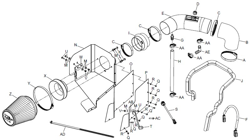
Shop Parts in this Guide
NOTE: FAILURE TO FOLLOW INSTALLATION INSTRUCTIONS AND NOT USING THE PROVIDED HARDWARE MAY DAMAGE THE INTAKE TUBE, THROTTLE BODY AND ENGINE.
TO START:
1. Turn off the ignition and disconnect the negative battery cable.
NOTE: Disconnecting the negative battery cable erases pre-programmed electronic memories. Write down all memory settings before disconnecting the negative battery cable. Some radios will require an anti-theft code to be entered after the battery is reconnected. The anti-theft code is typically supplied with your owner’s manual. In the event your vehicles’ anti-theft code cannot be recovered, contact an authorized dealership to obtain your vehicles anti-theft code.
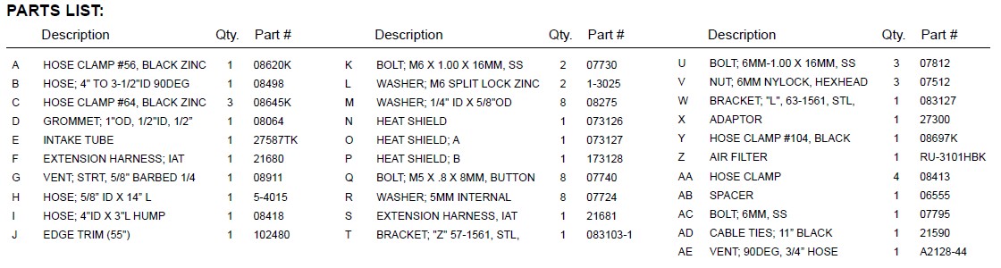
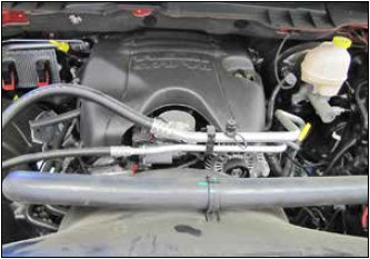
2. Disconnect the inlet air temperature sensor electrical connection.
3. Loosen the hose clamp securing the factory intake tube to the throttle body.
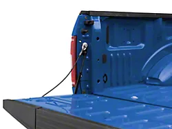
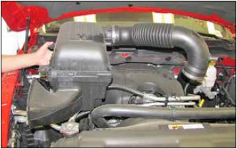
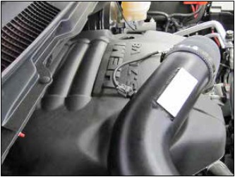
4. Disconnect the crank case vent hose from the upper air filter housing.
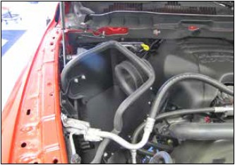
5. Disconnect the factory intake tube from the throttle body, then lift up the intake assembly and remove it from the vehicle.
NOTE: K&N Engineering, Inc., recommends that customers do not discard factory air intake.
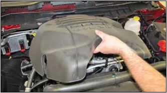
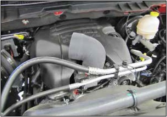
6. Lift up the engine cover and remove it from the vehicle.
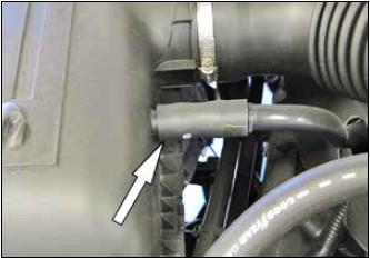
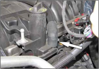
7. Disconnect the crank case vent hose assembly from the valve cover port.
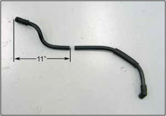
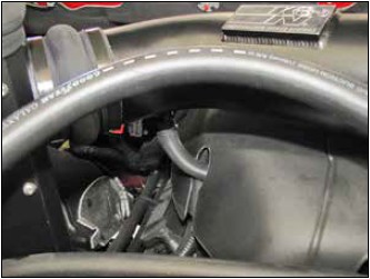
8. Measure 11” from the air filter end of the crank case vent hose and then trim the vent hose as shown.
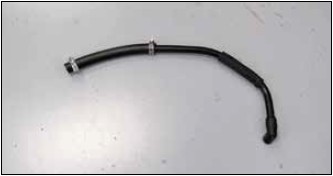
9. Install the provided vent hose onto the cut hose with the provided hose clamps as shown.
10. Reinstall the crank case vent hose assembly onto the valve cover.
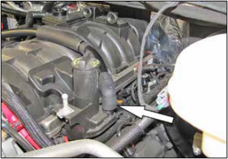
11. Reinstall the engine cover and route the crank case vent hose through the factory opening.
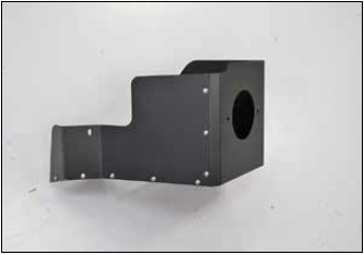
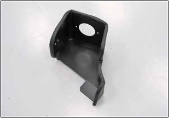
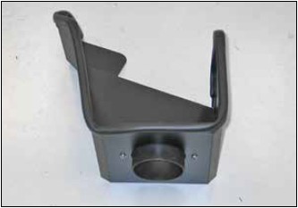
12. Choose the appropriate heat shield wall for the year model vehicle.
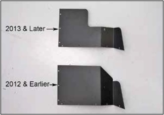
13. Install the heat shield wall onto the main heat shield and secure with the provided hardware.
14. Install the provided edge trim onto the heat shield as shown.
NOTE: Some trimming of the edge trim will be necessary.
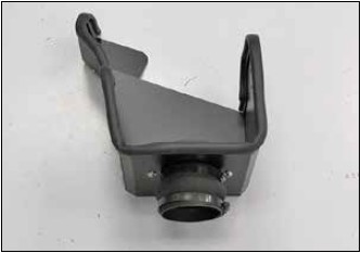
15. Install the provided filter adapter into the K&N® heat shield and secure with the provided hardware.
16. Install the provided silicone hose (08418) onto the filter adapter and secure with the provided hose clamp.
17. Install the provided mounting bracket (083127) onto the heat shield using the provided hardware.
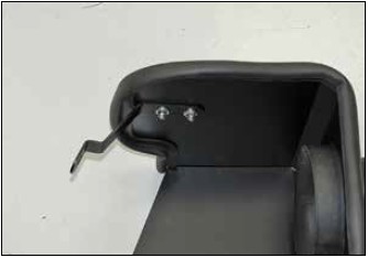
18. Install the heat shield mounting bracket (083103-1) onto the heat shield using the provided hardware.
NOTE: Do not completely tighten at this time.
NOTE: When using the cut out heat shield wall, place the provided spacer between the bracket and heat shield and use the longer bolt.
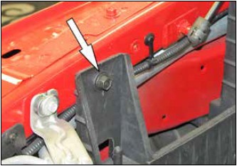
19. Remove the front air box mounting bracket bolt shown.
NOTE: This bolt will be reused in a latter step.
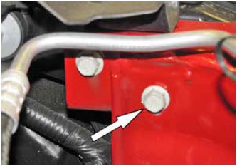
20. Remove the front fender mounting bolt shown.
NOTE: This bolt will be reused.
21. Install the heat shield into the vehicle and secure with the factory bolts from steps #19 and #20.
NOTE: Do not completely tighten at this time.
22. Install the provided silicone hose (08498) onto the throttle body and secure with the provided hose clamp.
NOTE: Do not completely tighten at this time.
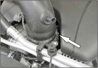
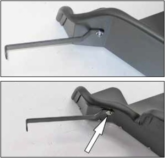
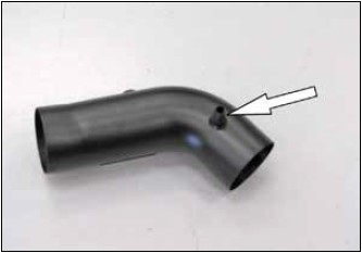
23. Install the provided grommet into the K&N® intake tube as shown.
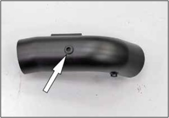
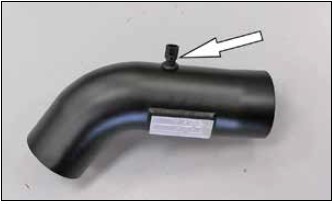
24. Install the vent fitting into the K&N® intake tube as shown.
NOTE: Plastic NPT fittings are easy to cross thread. Install the vent fitting “hand” tight, then turn it two complete turns with a wrench.
25. Remove the inlet air temperature sensor from the factory intake tube as shown.
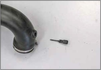
26. Install the inlet air temperature sensor into the grommet installed into the K&N® intake tube as shown.
27. Install the K&N® intake tube into the silicone hump hose and then align with the hose on the throttle body. Align the hose, tube and heat shield for proper fit and then secure with the provided hardware.
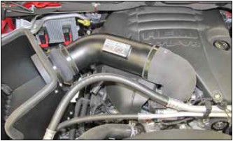
28. Connect the crank case vent hose to the fitting installed into the K&N® intake tube and secure with the provided hose clamp.
NOTE: Some trimming of the vent hose will be necessary.
NOTE: If the vent hose kinks, use the provided 90º fitting and additional hose clamps to route the hose free of kinks.
29. Choose the appropriate inlet air temperature sensor extension harness and then connect Install it too the inlet air temperature sensor and vehicle harness.
NOTE: The vehicle manufacturer uses two different inlet air temperature sensor connections, choose the correct extension harness for the sensor provided by the manufacturer. Secure the harness with the provided tie wrap.
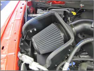
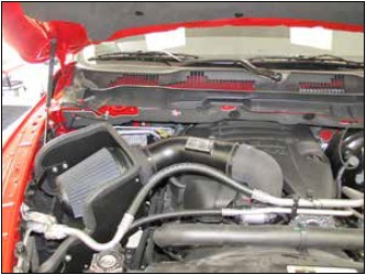
30. Install the K&N® air filter and secure with the provided hose clamp.
31. Reconnect the vehicle’s negative battery cable. Double check to make sure everything is tight and properly positioned before starting the vehicle.
32. The C.A.R.B. exemption sticker, (attached), must be visible under the hood so that an emissions inspector can see it when the vehicle is required to be tested for emissions. California requires testing every two years, other states may vary.
33. It will be necessary for all K&N® high flow intake systems to be checked periodically for realignment, clearance and tightening of all connections. Failure to follow the above instructions or proper maintenance may void warranty.
ROAD TESTING:
1. Start the engine with the transmission in neutral or park, and the parking brake engaged. Listen for air leaks or odd noises. For air leaks secure hoses and connections. For odd noises, find cause and repair before proceeding. This kit will function identically to the factory system except for being louder and much more responsive.
2. Test drive the vehicle. Listen for odd noises or rattles and fix as necessary.
3. If road test is fine, you can now enjoy the added power and performance from your kit.
4. K&N Engineering, Inc., requires cleaning the Blackhawk InductionTM intake system’s air filter element every 100,000 miles. When used in dusty or off-road environments, our filters will require cleaning more often. We recommend that you visually inspect your filter once every 25,000 miles to determine if the screen is still visible. When the screen is no longer visible some place on the filter element, it is time to clean it. To clean, purchase our Synthetic Filter Cleaner, part number 99-0624 and follow the easy instructions.