FREE 1 to 3-Day Delivery on Orders $149+ Details
How to Install K&N Brute Force Cold Air Intake - Polished on your Dodge Ram

Shop Parts in this Guide
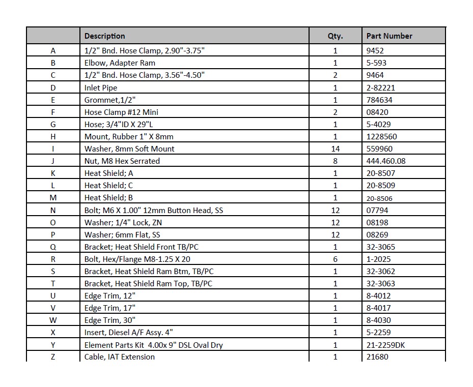
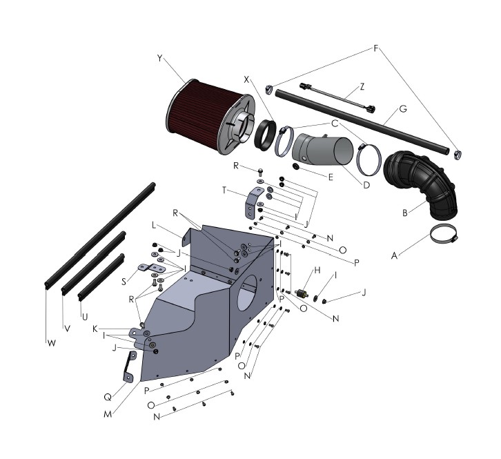
PARTS LIST
Read and understand these instructions BEFORE attempting to install this product. Failure to follow installation instructions and not using the provided hardware may damage the intake tube, throttle body and engine.
1. Preparing Vehicle
a. Make sure vehicle is parked on level surface.
b. Set the parking brake.
c. If engine has run in the past two hours, let it cool down.
d. Disconnect negative battery terminal.
e. Do not discard stock components after removal of the factory system.
f. Open the air intake kit package and make sure all parts are included.
2. Removal of stock system
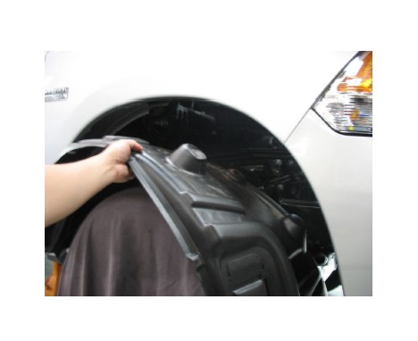
a. Remove all fasteners securing the passenger side fender liner. WARNING: After dropping the liner, be sure to unclip the ABS sensor wiring harness attached to the engine side of the liner.
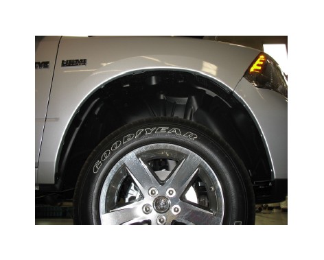
b. Remove the finder liner from the vehicle.
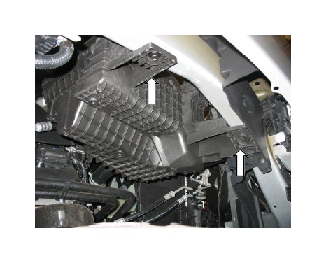
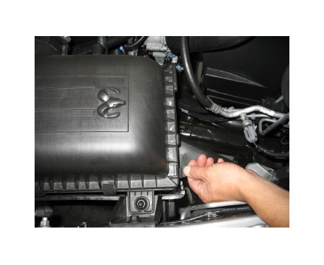
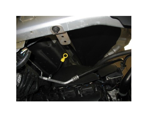
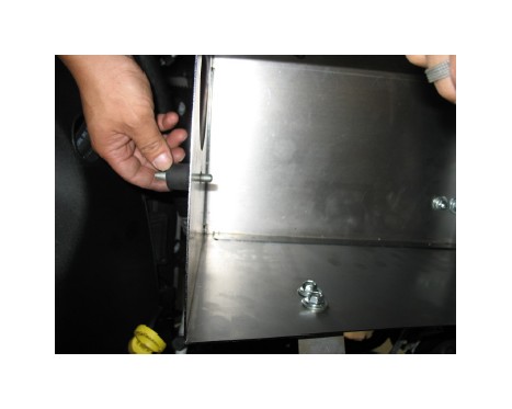
c. With the fender liner removed, access the air box from the bottom of the fender well and remove the 2 bolts securing the air box to the vehicle. Keep the bolts for use in a later step.
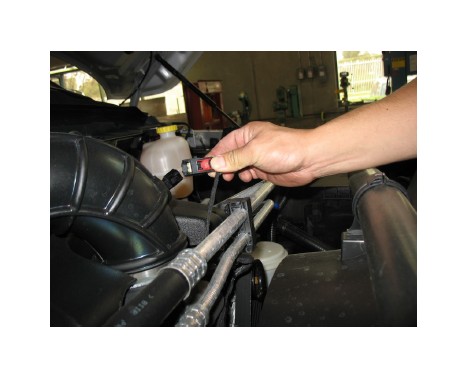
d. Unlock the intake air temperature (IAT) sensor con-nector by pressing the clip to disconnect the wiring har-ness from the sensor.
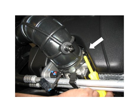
e. Loosen hose clamp securing the factory inlet duct to the throttle body.
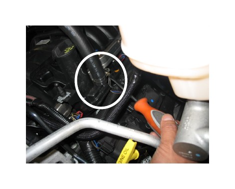
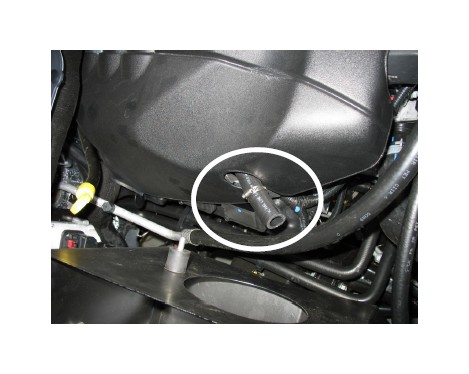
f. Disconnect the engine breather hose from the air box lid.
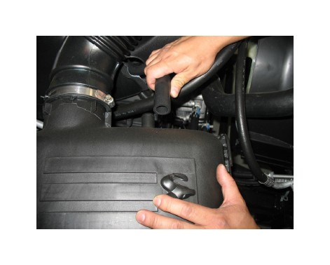
g. Unclip the air box lid from the air box base.
h. Remove the air box lid and inlet duct.
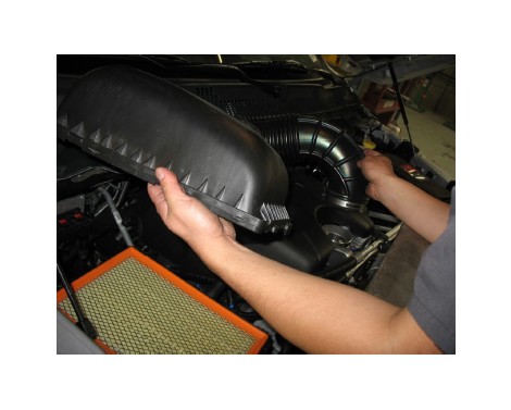
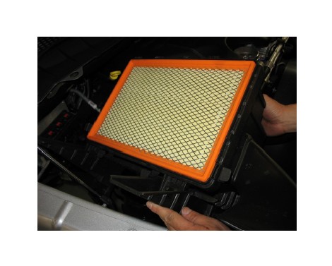
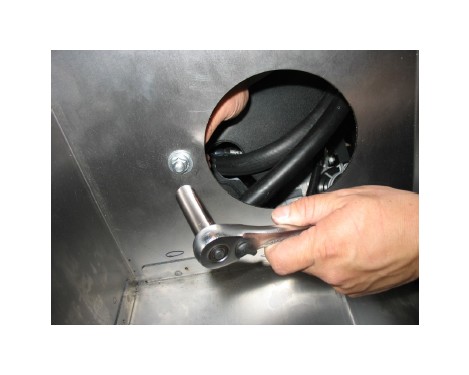
i. Remove the 2 bolts securing the air box base to the vehicle.
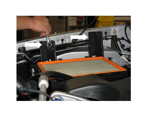
j. Remove the air box base and air filter from the vehicle.
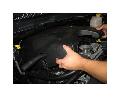
k. Remove the engine cover by lifting the front of the cover and then pulling forward.
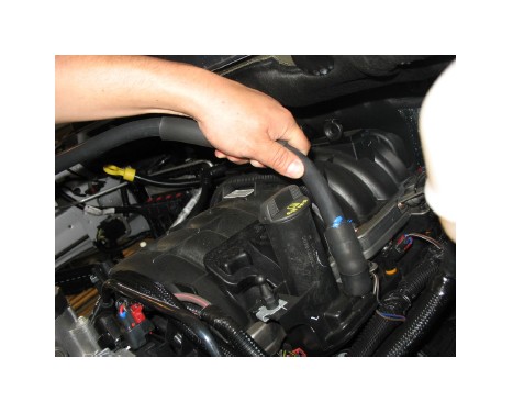
l. Remove the breather tube and hose from the engine.
a. Attach the rear heat shield panel “C” to the bottom heat shield panel “A” using 3 of each of the following: M6 x 12mm button head bolts, 6mm lock washers, and 6mm flat washers. Leave the bolts loose for now.
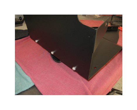
b. Here is another view of rear panel “C” attached loosely to bottom panel “A”.
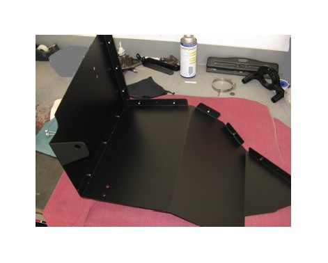
c. Now attach side Panel “B” to both panels “A” and “C” with 9 more M6 button head bolts, lock washers, and flat washers. Install the bolts loosely at first, then tighten them once the panels are in the correct position.
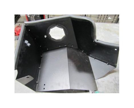
d. Here is the complete heat shield assembly. You may install the sponge rubber gaskets in the large hole (medium length gasket) and along the top edges (short and long gaskets) as shown at this time. Trim any excess as needed.
4. Installation of AEM® intake system.
a. When installing the intake system, do not completely tighten the hose clamps or mounting hardware until instructed to do so.
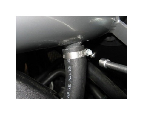
b. Install the ¾” ID hose and 1 ¼” hose clamp as shown.
c. With the hose fully engaged on the nipple, fully tighten the hose clamp.
d. Install the bottom heat shield bracket under the pas-senger side fender rail using the factory bolt removed from Step 2c.
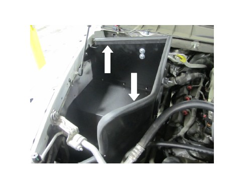
e. Carefully position the heat shield into the vehicle. Use the bolt removed in Step 2i to hold the heat shield in place. Tighten the bolt about ¾ of the way into the thread for now.
f. On the bottom side of the heat shield, secure the tab coming off the heat shield to the vehicle using the bolt removed in Step 2c. Tighten the bolt about ¾ of the way into the thread for now.
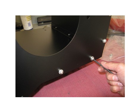
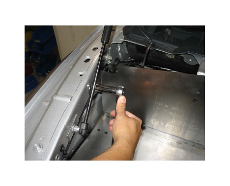
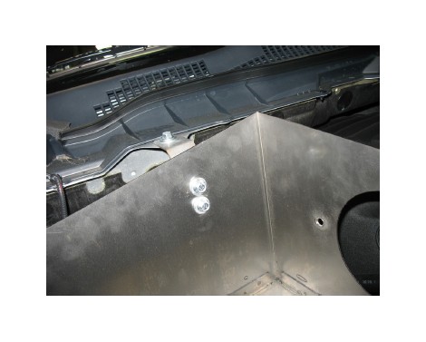
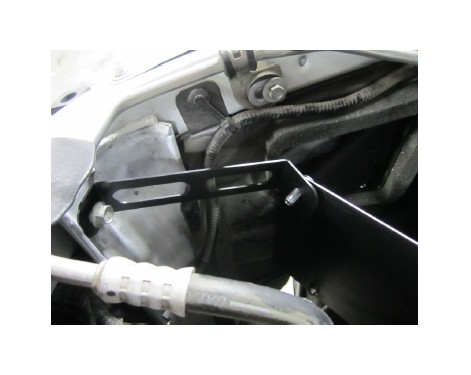
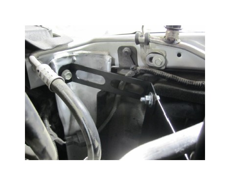
g. Install the rear bracket onto the top lip of the fire wall as shown. Use (Qty. 3) M8 x20mm bolts, (Qty. 3) nuts and (Qty. 6) washers to secure the bracket.
h. Here is another view of the rear bracket installation.
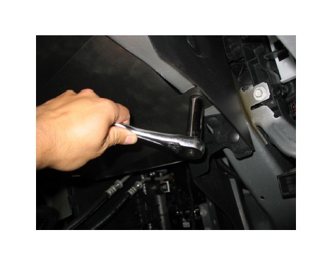
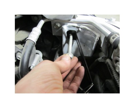
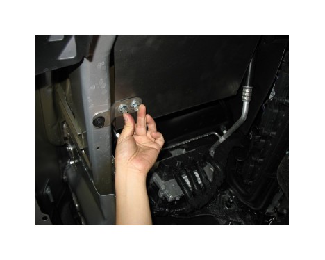
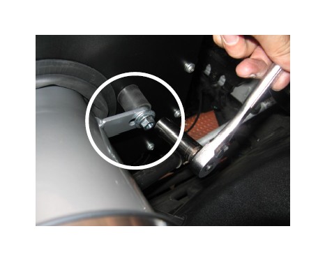
i. On the passenger side of the radiator support, re-move the long bolt as shown.
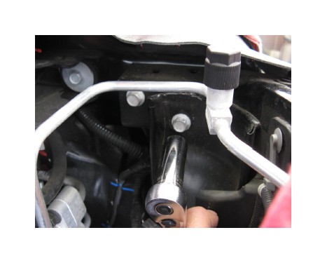
j. Secure the front tab of the bracket to the vehicle using the long bolt removed in step 4i.
k. Install the front bracket to the heat shield using an M8 x 20mm bolt, a nut, and 2 washers. The bracket has 2 bent tabs at its ends. Make sure the longer tab mates to the heat shield.
l. The front bracket should look as shown once properly installed.
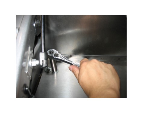
m. At the bottom bracket, hold 2 M8 bolts and 2 wash-ers in position, aligning the bracket to the heat shield.
n. Install 2 M8 washers and 2 M8 nuts to secure the bolts positioned in the previous step. Now go back and tighten all the heat shield bracket nuts and bolts installed.
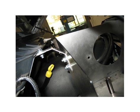
o. Install the rubber isolator mount on the outside of the heat shield assembly as shown.
p. Use 1 M8 washer and 1 M8 nut inside the heat shield to secure the rubber mount.
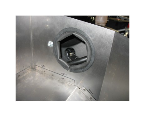
q. Install the medium section of the rubber sponge edge gasket in the large hole for the inlet tube as shown if you haven't done so previously.
r. Install the short and the long sections of the rubber sponge edge gasket along the top edge of the heat shield as shown if you haven't done so previously.
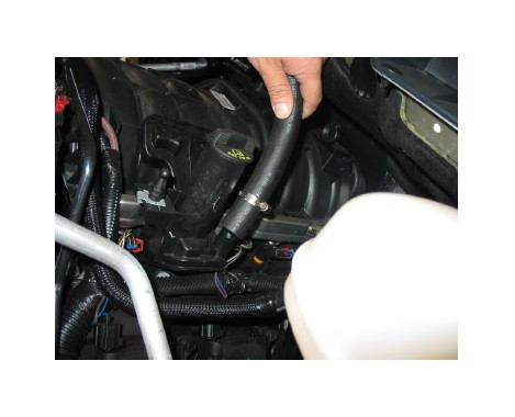
s. Re-install the factory engine cover, allowing the new breather hose to protrude from the access hole as shown. Place the second 1 ¼” hose clamp loosely on the end of the hose.
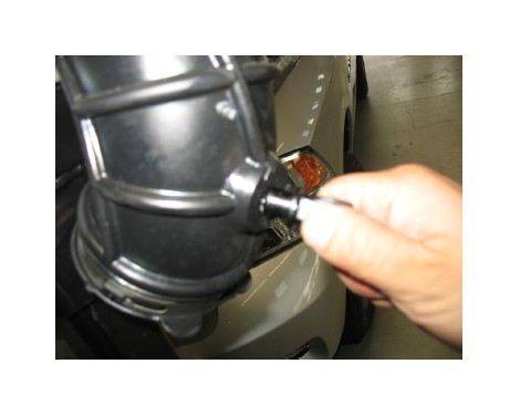
t. Carefully remove the inlet air temperature (IAT) sensor from the OEM inlet duct. Once removed, you will also need to remove the O-ring from the sensor. Note: Do not discard the O-ring, however it will not be re-used.
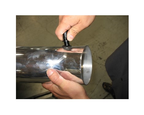
u. Carefully install the IAT sensor into the new inlet pipe using the supplied rubber grommet. If necessary, use soapy water to ease the installation of the grommet; install the IAT sensor into the grommet.
v. Loosely install hose clamps onto the intake adapter elbow as shown. Use hose clamp (9464) on the larger end and hose clamp (9452) on the smaller end.
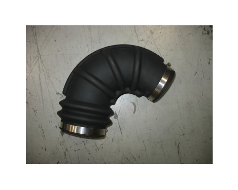
w. Install the inlet pipe into the adapter elbow, use soapy water to ease installation if necessary. Install the adapter insert into the open end of the inlet pipe.
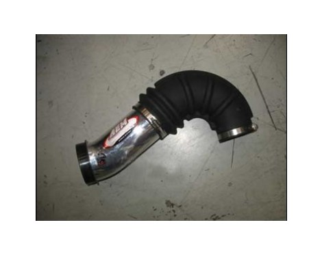
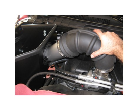
x. Install the intake pipe assembly, inserting the open end through the large hole in the heat shield while also mounting the elbow inlet onto the throttle body neck.
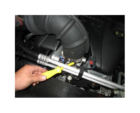
y. Tighten the smaller hose clamp of the elbow inlet at the throttle body.
z. Connect the IAT sensor cable extension to the origi-nal wiring harness. Connect the opposite end of the IAT sensor cable extension to the IAT sensor.
aa. Connect the breather hose to the nipple on the other side of the inlet tube and tighten the 1-1/4” hose clamp.
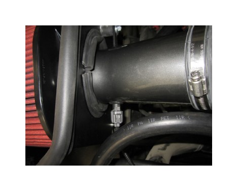
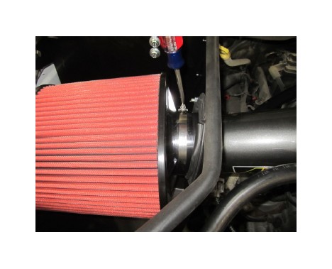
ab. Place the large hose clamp over the air filter’s inlet. Place the air filter inside the heat shield and then fully seat the filter onto the filter adapter. Insert the open end of the inlet pipe and loosely secure the hose clamp to hold the air filter in place.
ac. Shift the inlet pipe until the slot in the mounting bracket lines up with the isolator bolt mounted on the heat shield. Place one 8mm flat washer and one M8 nut on the bolt and fully tighten. Now go back and fully tight-en the larger air filter and inlet pipe hose clamps.
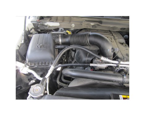
Factory air box system installed
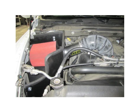
AEM® intake system installed
5. Reassemble Vehicle
a. Fender liner: Install the fender liner and any hardware that was removed in steps 2a through 2b. Make sure the ABS wiring harness is reattached to the engine-side surface of the fender liner. NOTE: Failure to install the fender liner will result in diminished performance and increase the potential for engine damage due to water ingestion in rainy conditions.
b. Position the inlet pipes for the best fitment. Be sure that the pipes or any other components do not contact any part of the vehicle. Tighten the rubber mount, all bolts, and hose clamps.
c. Check for proper hood clearance. Re-adjust pipes if necessary and re-tighten them.
d. Inspect the engine bay for any loose tools and check that all fasteners that were moved or removed are properly tightened.
e. Reconnect negative battery terminal and start engine. Let the vehicle idle for 3 minutes. Perform a final inspection before driving the vehicle.
6. CARB Sticker Placement
a. The C.A.R.B. exemption sticker, (attached), must be visible under the hood so than an emissions inspector can see it when the vehicle is required to be tested for emissions. California requires testing every two years, other states may vary.
7. Service and Maintenance
a. AEM Induction Systems requires cleaning the intake system’s air filter element every 100,000 miles. When used in dusty or off-road environments, our filters will require cleaning more often. We recommend that you visually inspect your filter once every 25,000 miles to determine if the screen is still visible. When the screen is no longer visible some place on the filter element, it is time to clean it. To clean, purchase our Synthetic air filter cleaner, part number 99-0624 and follow the easy instructions.
b. Use window cleaner to clean your powder coated AEM® intake tube.
NOTE: DO NOT USE aluminum polish on powder coated AEM® intake tubes.