FREE 1 to 3-Day Delivery on Orders $149+ Details
How to Install Rough Country 6 in. Suspension Lift Kit on your Ram
Installation Time
1 days
Tools Required
- WD-40
- Loc-Tite
- Reciprocating Saw
- Hammer
- Dead Blow Hammer
- T30 Torx head bit
- 5mm Allen Wrench
- 8mm Socket / Wrench
- 10mm Socket / Wrench
- 13mm Socket / Wrench
- 14mm Socket / Wrench
- 15mm Socket / Wrench
- 16mm Socket / Wrench
- 18mm Socket / Wrench
- 19mm Socket / Wrench
- 21mm Socket / Wrench
- 22mm Socket / Wrench
- 24mm Socket / Wrench
- 35mm Socket
- 9/16” Socket
- 1 1/16” Socket
INSTALLATION INSTRUCTIONS
1. Chock rear wheels of the vehicle and raise the front of the vehicle using a floor jack.
2. Support the vehicle with jack stands.
3. Remove wheel using 22mm socket.
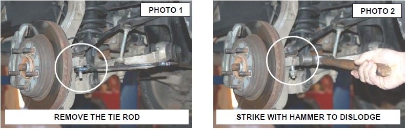
4. Remove tie-rod end nut using 21mm as shown in Photo 1.
5. Strike with hammer to dislodge the tie rod from the knuckle. See Photo 2.
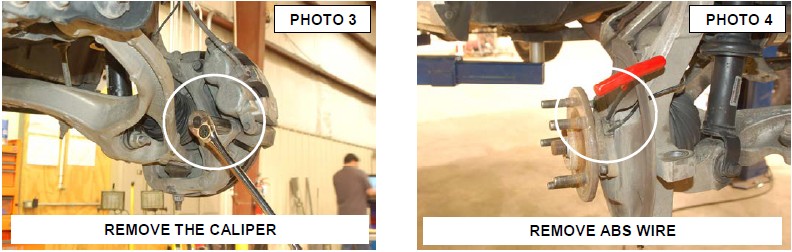
6. Remove brake caliper using 21mm wrench. See Photo 3. Secure out of way and remove rotor.
7. Remove ABS wire from hub using 5mm allen wrench, unclip ABS wire from knuckle also. See Photo 4.
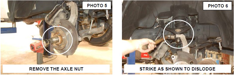
8. Remove axle nut using 35mm socket. See Photo 5.
9. Remove knuckle using 21mm wrench for top ball joint and 24mm wrench for lower ball joint. Strike with hammer as shown to dislodge the ball joints. Upper Joint shown in Photo 6.
10. Remove the stock knuckle from the truck. Take care not to allow the shaft to over extend.
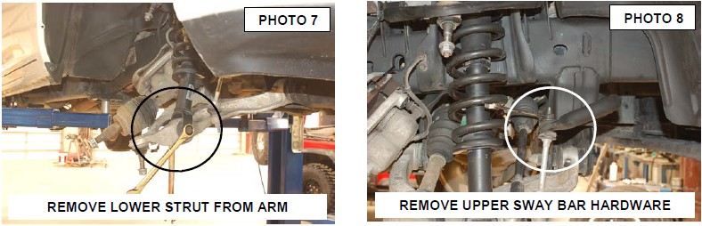
11. Remove lower strut mount using 21mm and 24 mm wrench. See Photo 7.
12. Remove sway-bar link from sway-bar using 16mm wrench. See Photo 8.
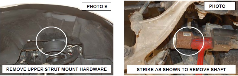
13. Remove upper strut mount using 15mm wrench and remove strut. See Photo 9.
14. Using a dead blow hammer remove axle from diff. See Photo 10.
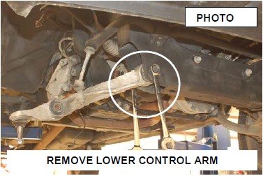
15. Using 24mm wrenches remove lower control arm. Retain the stock hardware for reuse. See Photo 11.
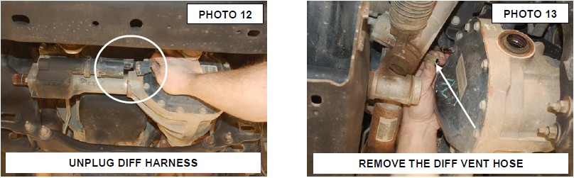
16. Unplug diff wiring harness from the differential. See Photo 12.
17. Remove vent hose from the differential. See Photo 13.
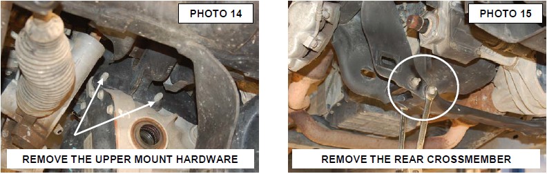
18. Remove the two upper diff bolts from the motor mount / diff mount using 18mm socket. These bolt can be very hard to access. Also the diff mount may be threaded or nuts may be present depending on engine size and year model. Retain the stock hardware if nuts are present. Use 15mm and 18mm wrench to remove hardware from motor mount /engine mount when nuts are present. If mount is threaded the hardware will not be retained. See Photo 14.
19. Remove rear cross-member using 18mm wrench. See Photo 15.
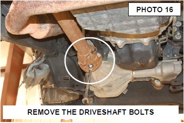
20. Remove driveshaft from diff using 15mm wrench. See Photo 16.
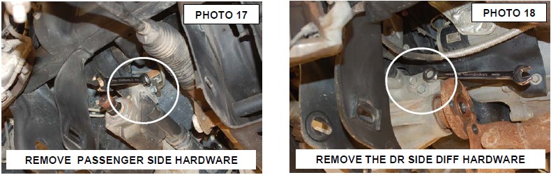
21. Support the diff and remove the passenger side bolts with 18mm and/or 15mm wrench and remove the 3 bolts on driver side with same wrenches. See Photo 17 & 18.
22. Carefully remove differential from vehicle.
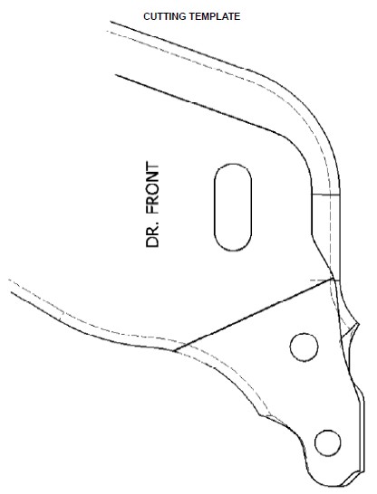
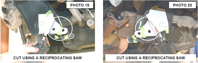
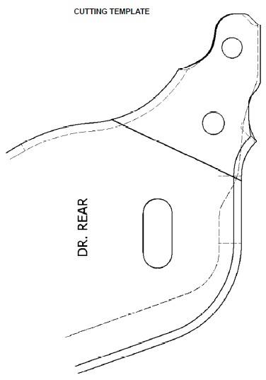
23. Align the supplied template with the lower holes. Tape cut out to driver side lower control arm rear pocket.
24. Cut at the line on the cut out. this is done to make room for rear cross member. Grind sharp edges and paint. See Photo 19 & 20.
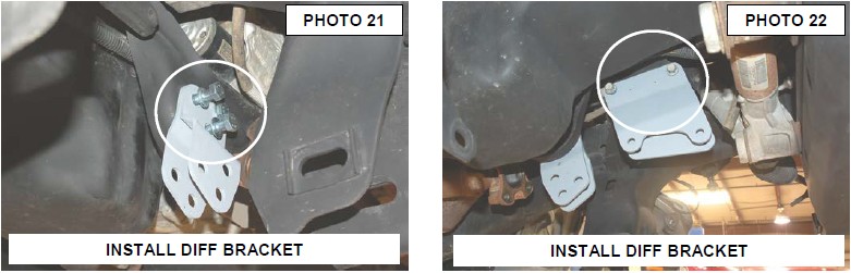
25. Install rear diff drop brackets using 3 supplied 12mm x 45mm bolts, washers. See Photo 21. Do not tighten at this time.
26. Install upper diff drop bracket using 2 of the stock driveshaft bolts. See Photo 22.Do this only if the motor mount / diff mount is threaded. If not threaded use stock hardware removed from diff / engine mount. Do not tighten at this time.
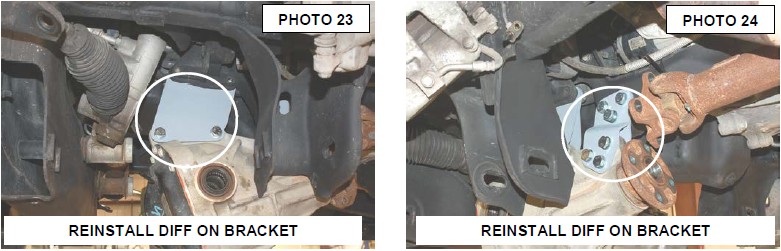
27. Install diff in both drop brackets as shown in Photo 23 & 24 using supplied 12mm x 65mm bolts, washers and nuts. Do not tighten at this time.
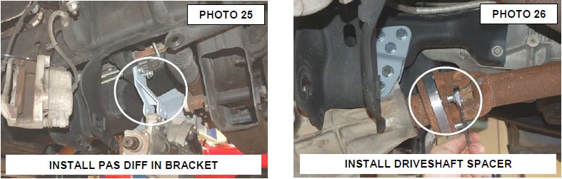
28. Install passenger side diff bracket using stock hardware in upper location if motor mount is threaded . If not use supplied 12mm x 65mm bolts for top and bottom of pass diff side. See Photo 25.
29. Tighten all diff bolts at this time using wrenches 15mm for upper diff bracket and 18 an 19mm for all other diff bolts.
30. Apply thread lock to supplied 12mm x 45mm bolts and install driveshaft spacer. Use a 19mm wrench to tighten. See Photo 26.
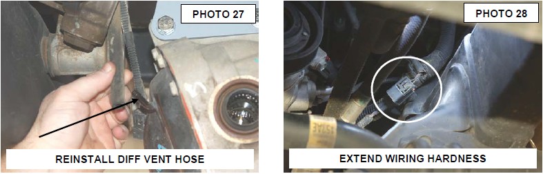
31. Pull down on vent hose for slack and reconnect. See Photo 27.
32. Follow the diff wire upper to a second connector and undo the clip holding it to the engine wiring harness and pull down until you have slack to plug in diff connector. See Photo 28. On 4.7 engines pull clip off of valve cover bolt behind power steering pump to gain slack. Be sure wire is not near exhaust.
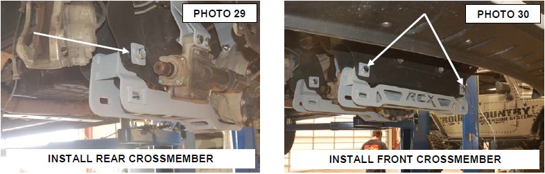
33. Install rear cross member using supplied 18mm x 150mm bolts, square washers and nuts. See Photo 29.
34. Install front cross member using supplied 18mm x 150mm bolts, square washers and nuts. See Photo 30. Do not tighten at this time.
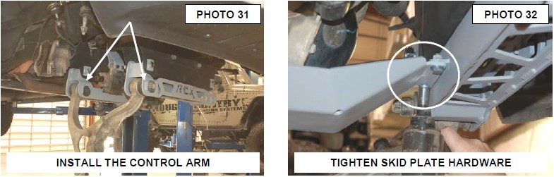
35. Install lower control arm using stock cam bolts. See Photo 31.
36. Install skid plate using supplied 3/8” X 1” bolts and 3/8” washers on the front cross-member. Use 14mm socket to tighten. See Photo 32.
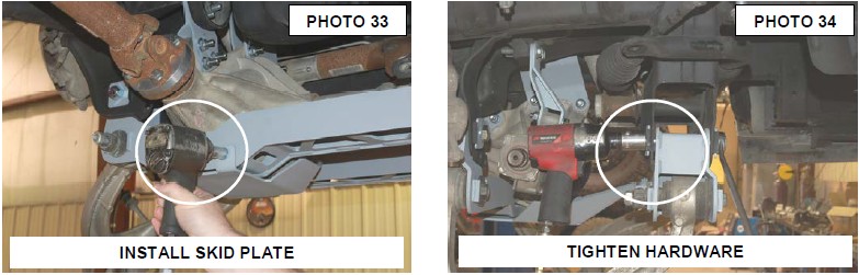
37. Install the skid plate on the rear cross-member as shown in Photo 33 with the supplied 3/8” x 1” and washers.
38. Using 1 1/16 wrench and socket tighten cross member bolts. See Photo 34.
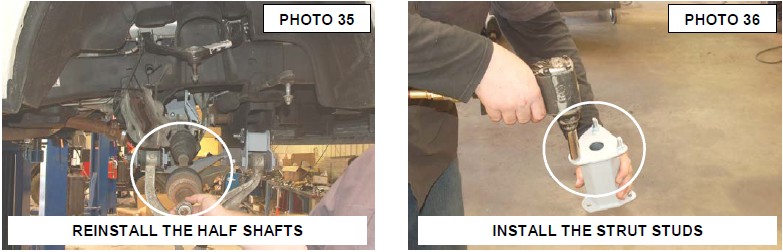
39. Install axle shafts making sure the axle is fully engaged in the housing. See Photo 35.
40. Install 10mm studs into strut spacer using 17mm socket. See Photo 36. It may be necessary to lightly tap studs in.
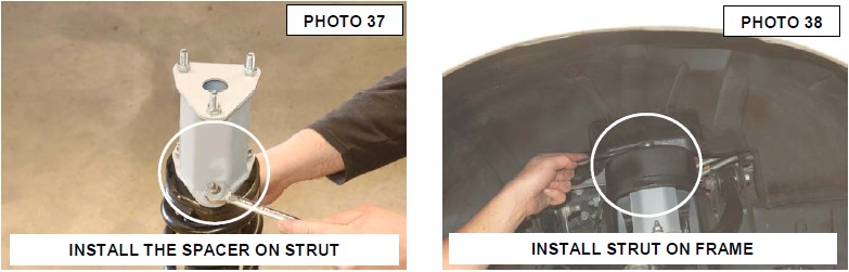
41. Install the spacer on strut using stock hardware using 15mm wrench. See Photo 37.
42. Install strut onto truck using 17mm wrench to tighten upper supplied 10mm nuts and washers See Photo 38.
43. Attach lower control arm to lower part of strut using stock hardware. Tighten lower strut hardware using a 24mm and 21 mm wrench. See Photo 39.
44. Remove sway-bar link from control arm using 18mm and 8mm wrench.
45. Install the lower link bracket on the lower control arm with the supplied 12mm X 50mm bolt and flange nuts. Install the new link on the bracket with the supplied 12mm x 65mm bolts and flange nuts. Tighten using a 18mm and 19mm socket & wrench. See Photo 40.

46. Install the sway bar link bracket to the bottom side of the sway bar and tighten with the 12mm x 35mm bolts and flange nut. Tighten using a 18mm and 19mm wrench. Next install the sway bar link to the bracket and tighten using the 12mm x 65mm bolts and flange nuts. See Photo 41.
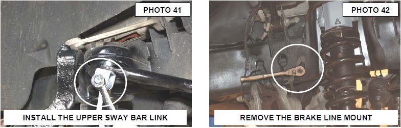
47. Using a 13mm wrench remove bolt from brake line mount and pull brake line out to give clearance for cutting. See Photo 42.
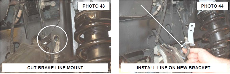
49. Notch a section of the stock mount to remove the brake line as shown in Photo 43 and remove line from housing. Straighten bends in hard metal lines making sure to not kink lines.
50. Install new brake line bracket onto brake line using supplied 5/16” x 3/4” bolts, washers and nuts. See Photo 44.
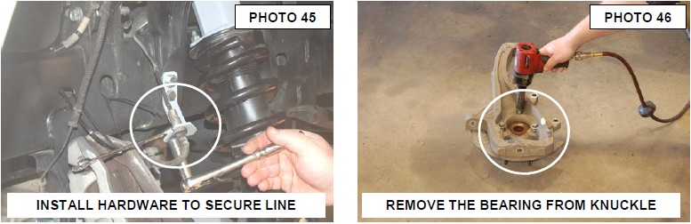
51. Then attach bracket to frame using stock bolt in lower hole and new supplied 3/8” x 1” bolts, washers and nuts. See Photo 45. Use a 13mm wrench to tighten stock bolt and lower brake line bolt then use a 14mm on top 3/8” bolt.
52. Remove bearing assembly from the stock knuckle using 18mm socket. See Photo 46.
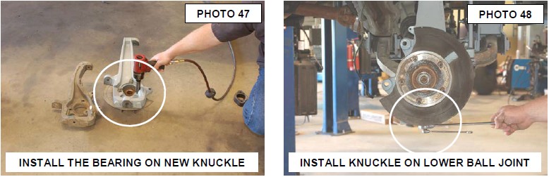
53. Install bearing into new knuckle using stock bolts and a thread locking compound. See Photo 47.
54. Install new knuckle onto truck using a 24 and 12mm wrench for lower ball joint. See Photo 48.
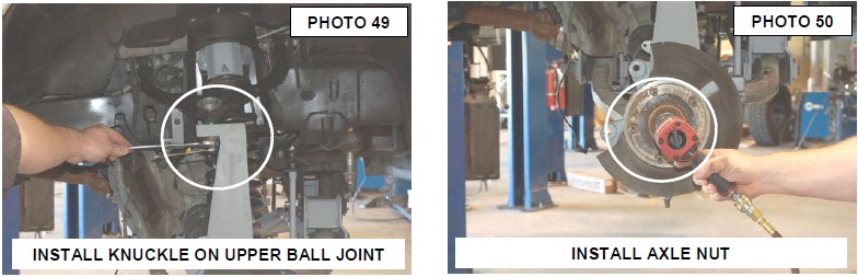
54. Slide the axle in the bearing assembly and install the knuckle on the upper ball joint using a 21mm and 10mm wrench. See Photo 49.
55. Tighten the axle nut using a 35mm socket. See Photo 50.
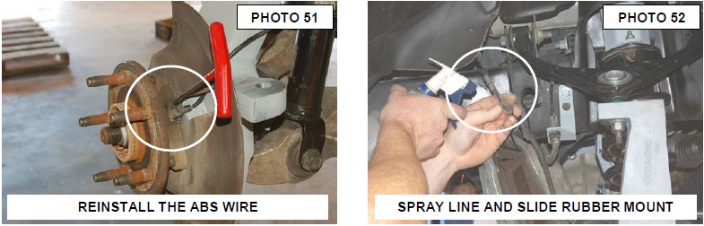
56. Unclip ABS wire from upper control arm and install wire back into bearing assembly using 5mm allen wrench. See Photo 51.
57. Using WD-40 move the rubber insulator into right spot and clip back into upper control arm. See Photo 52.
58. Install rotor and brake caliper. Use a 21mm socket to tighten caliper.
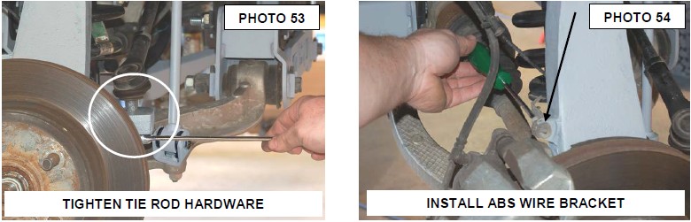
59. Install tie rod into knuckle using 21mm wrench. See Photo 53.
60. Using a T30 bit remove ABS wire bracket from old knuckle and install on new one. Reinstall the ABS wire on the mount. See Photo 54.
61. Repeat steps 38-57 for opposite side.
62. Install tires and wheels.
63. Remove the jack stands and lower the vehicle to the ground.
64. Tighten lower control arm hardware using a 24mm socket / wrench
REAR INSTALLATION INSTRUCTIONS
1. Chock the front tires. Raise rear of the vehicle with floor jack.
2. Support the rear with jack stands
3. Remove wheels using a 22mm socket.
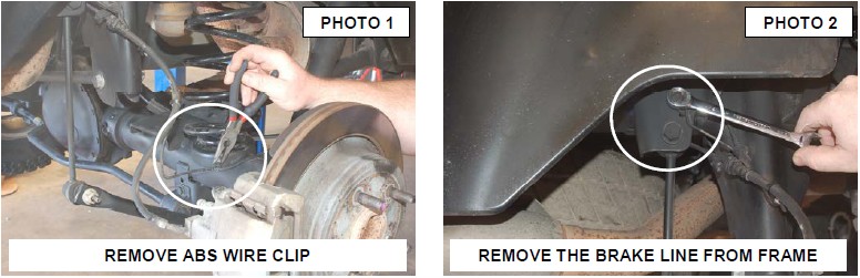
4. Remove ABS clip from axle. See Photo 1.
5. Remove the brake line as shown in Photo 2 using 13mm.
6. Remove sway-bar link using 8mm and 18mm wrench for lower end and 18mm for top end. See Photo 3 & 4.
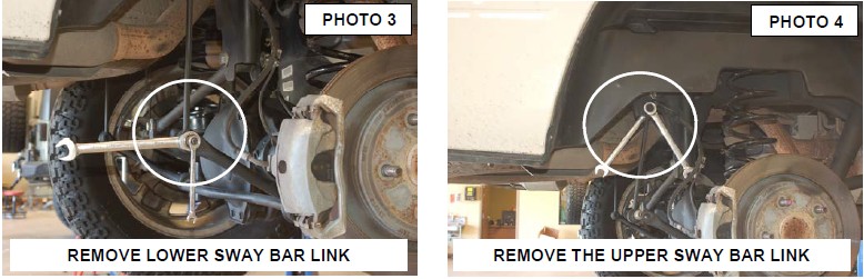
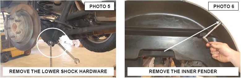
7. Remove the shocks from the axle using 21mm wrench. See Photo 5.
8. To remove the upper shocks from the frame mount, remove the inner fender well using 8mm socket. See Photo 6. There are 10 bolts on driver side and 10 on passenger side. This is done to gain access to nut on back of shock. Use a socket on back side to remove bolt.
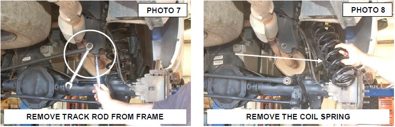
9. Remove upper track bar bolt using 21mm wrench. See Photo 7.
10. Remove the vent hose from the frame.
11. Remove coil springs and isolators. See Photo 8.
12. Remove the upper control arm using 24mm wrench and socket on the frame and axle. See Photo 9 & 10.
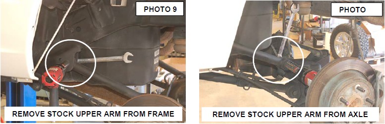
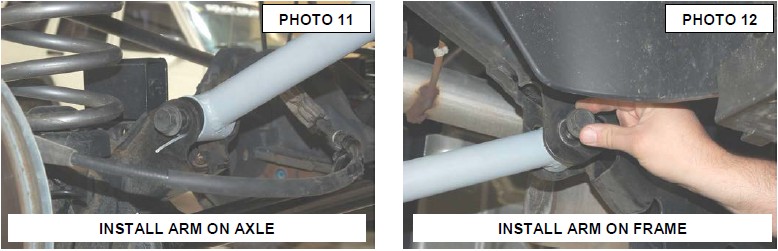
13. Install control arm in the axle and frame mounts with stock hardware. Tighten using 24mm wrench. See Photo 11 & 12.
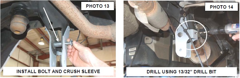
14. Install track bar bracket using supplied crush sleeve,14mm x 80mm bolt, washers and nut See Photo 13. Do not tighten at this time. Make sure the bracket is installed correctly placing the lower hole in the new bracket directly below the stock hole. Failure to install this bracket correctly will push the axle out of center.
15. Use bracket to mark the side hole to be drilled. Drill the hole on the side of the bracket using a 13/32 drill bit. See Photo 14.
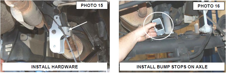
16. Install the 3/8” x 1 1/4” Bolt, washers & nut on the side hole. Tighten using a 14mm socket / wrench. See Photo 15.
17. Double check to make sure the bracket is still in position.
18. Drill the other two upper holes using a 13/32” drill bit and install supplied 3/8” x 1 1/4” bolts, washers and nuts. Tighten using a 14mm wrench / socket.
19. Install bump stops using supplied 3/8” x 1” bolts, washers and nuts. The pin in the block goes in front hole as shown in Photo 16. Tighten hardware using a 14 mm wrench.
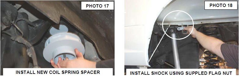
20. Install the round retainer washer from the top side of the upper coil pocket. Using the supplied 3/8” x 5.0” bolt, insert the bolt through the center hole of the rear coil spacer and tighten with a 9/16” socket. See Photo 17. Next install the factory coil spring and isolator.
21. Install bushing a sleeves into shocks. Install shock onto truck using stock hardware with supplied flag nut for top bolt. See Photo 18.
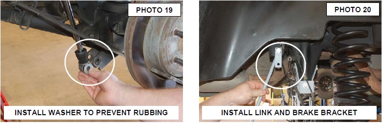
22. Also install washer on bottom of shock to the outside of truck. See Photo 19. Use 21mm to tighten.
23. Pull down and straighten brake line. Take care not to kink the brake line.
24. Install sway bar links & brake line brackets on the frame with the supplied 12Mm x 65mm bolts, washers and nut. See Photo 20.
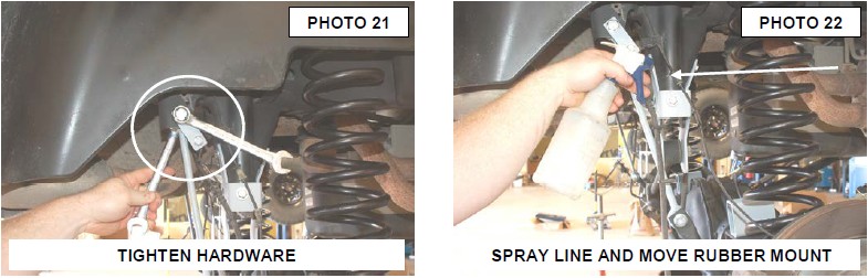
25. Install stock brake line mount on the bracket using the supplied 5/16” x 3/4” bolt, washers and nut. See Photo 21. Use a 18mm and 19 mm to tighten sway bar link bolts and 13 mm for brake line bolts.
26. Install track bar into bracket with stock hardware. You may have to do this with truck on the ground. Tighten upper bolt using 22mm wrench and lower with 21mm wrench.
27. With WD-40 or alcohol adjust the rubber insulator on ABS wire so that it will fit back into clip on brake line. See Photo 22.
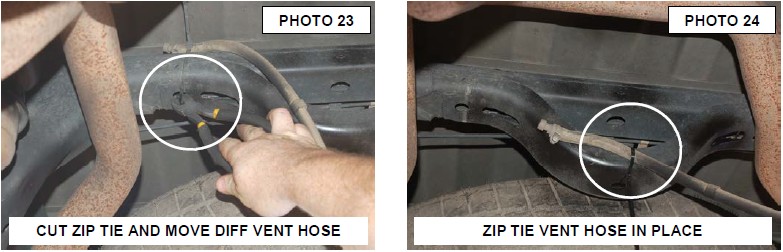
28. If not removed previously, Cut zip tie for axle vent tube and install new zip tie and vent tube on lower part of frame. See Photo 23 & 24.
29. Reinstall fender wells using 8mm socket.
30. Check to make sure all fasteners are tight.
POST INSTALLATION
1. Check all fasteners for proper torque. Check to ensure there is adequate clearance between all rotating, mobile, fixed and heated members. Check steering for interference and proper working order. Test brake system.
2. Perform steering sweep. The distance between the tire sidewall and the brake hose must be checked closely. Cycle the steering from full turn to full turn to check for clearance.
3. Re torque all fasteners after 500 miles. Visually inspect components and re torque fasteners during routine vehicle service.
4. Readjust headlights to proper settings and take truck in for a front-end alignment to a qualified alignment professional.