 FREE 1 to 3-Day Delivery on Orders $149+ Details
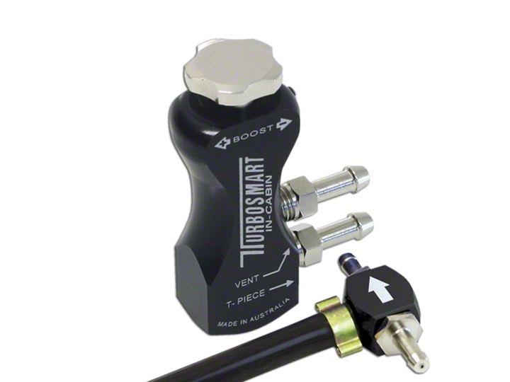
How to Install Turbosmart In Cabin Boost Controller - Black (97-18 All) on your Ford F-150
Shop Parts in this Guide
1) INTERNAL WASTEGATE SETUP
1. Allow the engine to cool down before installing your boost controller
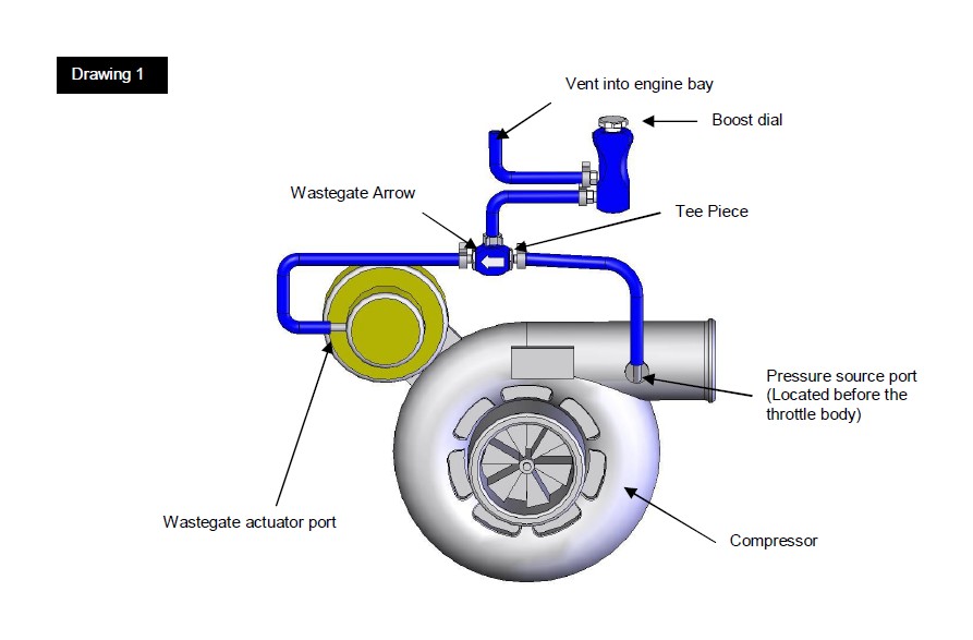
2. Locate the pressure source port and the wastegate actuator port on the turbocharger assembly (refer drawing 1)
3. Remove the factory boost control solenoid if fitted from the boost pressure supply port while leaving the solenoid connected to the ECU
4. Install the tee piece in the wastegate pressure line with the wastegate arrow pointing towards the wastegate actuator and run the tee piece pressure line into the cabin and connect it to the bottom port of the boost controller
5. Run a second pressure hose line from the engine bay into the cabin and connect it to the top vent port
6. If your wastegate actuator has additional ports, these will need to be blocked
7. Secure all silicone hose ends with hose clamps
8. Mount your boost controller bracket inside the vehicle cabin, then attach the boost controller onto the bracket with the supplied screws
9. Make sure the boost dial is turned completely anti-clockwise before making adjustments.
2) EXTERNAL WASTEGATE SETUP
1. Allow the engine to cool down before installing your boost controller
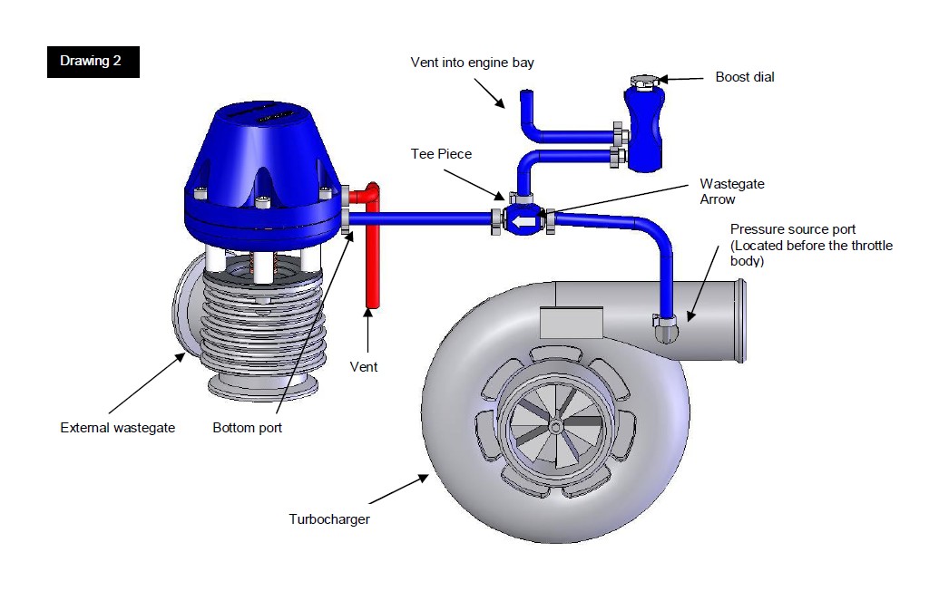
2. Locate the bottom port on the external wastegate and the pressure source port (refer Drawing 2)
3. Install the tee piece onto the bottom port of the wastegate as per the 4th step in the internal wastegate setup
4. Follow the 5th – 9th step of the internal wastegate setup
3) PARALLEL TWIN TURBO SETUP
1. Allow the engine to cool down before installing your boost controller
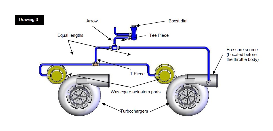
2. Locate the wastegate actuator ports on both turbochargers and a pressure source port (refer Drawing 3)
3. Remove the factory boost control solenoid if fitted from the boost pressure supply line
4. Install your boost controller tee piece in the wastegate pressure line with the wastegate arrow pointing towards the wastegate actuators as per step 4 in the internal wastegate setup instructions
5. Be sure to keep the hoses joining the wastegate actuators at equal lengths
6. Follow the 5th – 9th step of the internal wastegate setup
IMPORTANT NOTES ON BOOST PRESSURE ADJUSTMENT
• Adjustment to your boost controller is made by rotating the Boost Dial
• Rotate in a clockwise direction to increase boost and the reverse direction to decrease boost
• Before making any adjustment, the Boost Dial will need to be fully closed (anti-clockwise)
Step 1: Apply full load to the engine in a high gear (at least 3rd or 4th gear) at full throttle and note the boost pressure
Step 2: To increase boost rotate the Boost Dial clockwise (maximum of 1 complete revolution at a time)
Step 3: Apply full load to the engine and note the boost pressure
Step 4: Compare the actual boost pressure with the desired boost pressure. If the actual pressure is below the desired pressure, return to step 2. If the actual is above the desired boost then decrease by rotating the Boost Dial anti-clockwise and return to step 3.
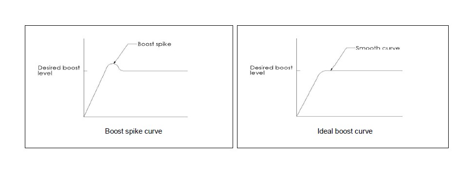
BOOST SPIKING
If boost spiking occurs and is undesirable for your application, the gate system can be removed to give you a less aggressive boost curve. This modification is only required in a minimal number of applications.
IMPORTANT NOTES ON GATE SYSTEM REMOVAL
The gate system can be removed by the following steps.
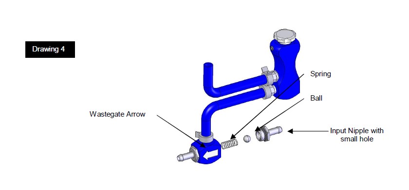
Perform this modification on a clean bench so that the ball and spring are not lost
• Allow the engine to cool down before removing the Tee piece from your vehicle
• Identify the input nipple with the restrictor at the end. Loosen the input nipple and remove the ball and spring.
• Check that the internal air passages are clear and free from debris
• Re-install the boost controller by following the instructions for your setup
• You will need to re-adjust your boost settings after the removal of the gate.
TROUBLE SHOOTING
The following points should be checked if you find that your engine is developing excessive boost, the boost pressure is fluctuating or the desired boost level cannot be achieved. Please note the following checks will cure 99% of problems experienced when fitting a Turbosmart boost controller.
• Check that the boost controller is installed so that the arrow points toward the wastegate actuator
• Check the joining hoses for splits, cracks or loose connection and are the correct size for the application
• Check to see if the boost controller is blocked or contaminated with dirt or debris
• Ensure that there is nothing but the boost controller in the hose between the pressure source and the wastegate actuator, ie tee pieces for boost gauge or to factory boost solenoid.
• Pressure test the wastegate actuator for leakage, the diaphragm or housing may be cracked or split
• Check that the wastegate is operating correctly


