FREE 1 to 3-Day Delivery on Orders $149+ Details
How to Install Flowmaster Force II Aluminized Steel Cat-Back Exhaust - Single Side Exit

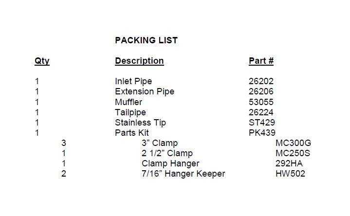
Shop Parts in this Guide
Removal:
1) Raise the vehicle up on a hoist or rack to working height. If you do not have access to a hoist or rack raise the vehicle and support securely with jack stands.
2) Using a hacksaw or sawsall, cut the stock tailpipe off where it exits the muffler. Remove the hanger at the rear of the tailpipe from the rubber mount on the vehicle and set the tailpipe aside. (This step is not mandatory, but will make removal easier.)
3) Support the muffler with a stand and remove the hanger at the rear of the muffler along with the hanger in front of the muffler from the rubber mounts on the vehicle. Loosen the bank that secures the factory inlet pipe to the converter y-pipe. Once loose, slide the muffler off of the front pipe and set aside.
Installation:
1) Before installing anything, prep the clamps supplied in the hardware kit by removing the nuts, and applying a thick lubricant such as white grease or anti-seize to the threads.
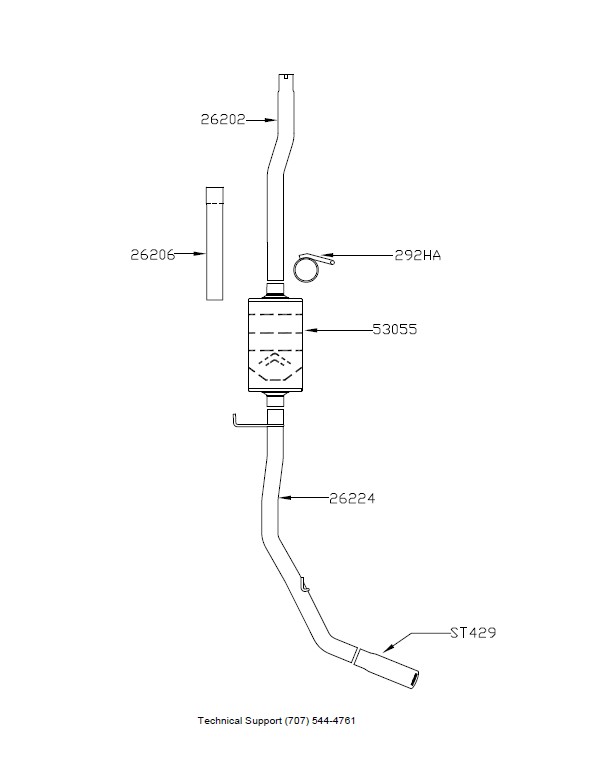
2) Depending on your cab/bed configuration, the inlet pipe #26202 may need to be trimmed to accommodate the difference in wheelbase length. Double check all measurements before cutting your inlet pipe:
Regular Cab
6.5’ Bed = Trim 18.50” from the rear of inlet pipe 26202.
8.0’ Bed = Requires no trim of the inlet pipe.
Super Cab
5.5’ Bed = Trim 12.0” from the rear of inlet pipe 26202.
6.5’ Bed = Requires no trim of the inlet pipe.
8.0’ Bed = No trim required, add 26206 ext. pipe
Super Crew
5.5’ Bed = Trim 6.0” from the rear of inlet pipe 26202.
6.5’ Bed = No trim required on 26202. Add extension pipe 26206 and trim 12.0” off of it.
3) Slide a 2 1/2” clamp #MC250S over the reduced end of the inlet pipe. Then place the inlet pipe onto the back of the existing OEM head pipe (by lining up the notch). Tighten the clamp just enough to hold the pipe in place.
4) Slide the inlet hanger #292HA over the back of the inlet pipe and insert the hanger into the factory rubber mount. Tighten both clamps enough to hold, while still allowing for some adjustment.
Note: *Reg Cab/6.5’ Bed: This hanger is not used.
*Super Cab/6.5’ Bed, Super Cab/8.0’ Bed and Super Crew – The rubber mount is bolted to the side of the frame, and must be relocated forward to the cross brace where you will find another factory mounting hole location.
5) Slide a 3” clamp #MC300G onto the inlet neck of the muffler #53055. Then place muffler onto the inlet pipe and support with a stand. Tighten the clamp just enough to hold, while still allowing for adjustment.
6) Slide a 3” clamp #MC300G onto the muffler outlet neck. Place tailpipe #26224 into position over the axle and insert the hanger at the front and rear of the pipe into the rubber mounts on the vehicle and slide into the muffler outlet. Tighten the clamp just enough to hold, while still allowing for adjustment.
7) Place the stainless tip #ST429 onto the end of the tailpipe and adjust to the desired location. Then tighten the tip enough to hold but still allow for adjustment.
8) Adjust the position of all the pipes and muffler to provide a satisfactory fit. A minimum of 3/4” clearance around all parts of the system must be maintained; while keeping suspension travel and vibration in mind. After adjustments have been made, securely tighten all clamps and install the 2 push-on 7/16” hanger keepers #HW502 onto the hanger rods.
9) For a cleaner appearance and more secure installation, we highly recommend welding all slipfit connections. If you live in a geographical area that has harsh winters or sees a great deal of precipitation, the use of high temperature paint over the welded areas can help to prevent surface rust and premature corrosion.