FREE 1 to 3-Day Delivery on Orders $149+ Details
How to Install Auto Meter Factory Match Fuel Pressure Gauge - Digital Stepper Motor on your Ram

Shop Parts in this Guide
Installation - Fuel & Oil Pressure
WARNING: The fuel system is pressurized and often retains this pressure for an extended period of time. Properly vent your fuel system before installing the fuel pressure sender. If you are not familiar with the proper method of venting, you MUST have this done by an experienced mechanic.
1. Check that you have all parts required for installation, and the engine is cool.
2. Disconnect the negative (-) battery cable.
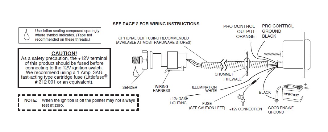
3. Gauge mounts in a 25⁄8” hole for 25⁄8” gauges, and a 21⁄16” hole for 21⁄16” gauges. Use supplied brackets and nuts to secure gauge to dash.
4. Drill 1” diameter hole where wires pass through sheet metal (such as firewall) and install rubber grommet provided. (Grommet will require slit.)
5. Connect the white wire to dash lighting or switchable 12v light source, the red wire to switched 12V source and the black wire to ground. (see diagram for details)
6. [For oil pressure gauge installation, an optional 1⁄4” NPT adapter is included. For fuel pressure gauge, install the 1⁄8” NPT pressure sender into the fuel system (See warning in next column). For Ford fuel injected applications with a Schrader valve in the fuel rail, use adapter 3280 between the fuel rail and pressure sender.] If unit is to be installed on a high vibration application such as a full race engine or engine capable of high RPM, it is strongly recommended that the sender be remote mounted to either the fenderwell or firewall, to insulate from vibration. Failure to remote-locate pressure senders on such an application could result in gauge failure and potential damage to vehicle and/or operator injury. Braided stainless steel lines are sold separately by Auto Meter, and can be used to accomplish this.
7. Reconnect negative (-) battery cable.
NOTE: Test all fittings and hoses for any leakage. If any leaks are detected, determine the cause of the leak and repair. Do not operate vehicle if any leaks are detected.
WARNING: Not compatible with Nitromethane, Methanol, or 100% MTBE.
CAUTION: If you will be working with the fuel system, take care to insure no sparks or flames occur. Do not smoke while installing the fuel pressure sender.
Installation - Nitrous Pressure
1. Check that you have all parts required for installation, & the engine is cool.
2. Disconnect the negative (-) battery cable.
3. Gauge mounts in a 25⁄8” hole for 25⁄8” gauges, and a 21⁄16” hole for 21⁄16” gauges. Use supplied brackets and nuts to secure gauge to dash.
4. Drill 1” diameter hole where wires pass through sheet metal (such as firewall) and install rubber grommet provided.
5. Connect the white wire to dash lighting or switchable 12v light source, the red wire to switched 12V source and the black wire to ground. (see diagram for details)
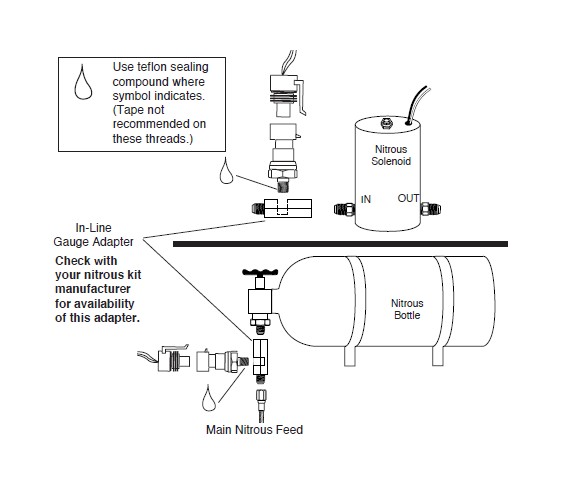
6. Make sure the nitrous bottle valve is closed and there is no pressure in the system.
7. Remove the main nitrous feed line from the bottle or the nitrous solenoid. Install the in-line gauge adapter (e.g. NOS part #16770 or #16771) either on the nitrous bottle or nitrous solenoid. Re- install the main nitrous feed line. Install pressure sender and wiring harness. For mounting off bottle in rear of car, use 20’ sender harness model 5223.
8. Open the nitrous bottle valve.
NOTE: Test all fittings and hoses for any leakage. If any leaks are detected, determine the cause of the leak and repair. Do not operate vehicle if any leaks are detected.
Power-Up
The pointer will move backward to the stop pin and then move to the zero box. This procedure is an auto-calibration function and is performed on every power-up. While this test is being performed, the gauge may make a clicking sound. This is normal.
Warning Indicator
To adjust the warning set point, momentarily press and release the WARN button. The warning light will begin to flash and the pointer will move to the previous set point signifying that warning set mode has been selected. Once in set mode, press the WARN button to move the pointer down, or press the PEAK button to move the pointer up. Three seconds after the last button press, the warning light will stop blinking and the pointer will return to the current pressure reading. The warning set point is retained when power is removed from the gauge. The warning set point is also the Pro Control set point. On gauges with full dial warning, the “warning indicator” and “warning light” refers to the full dial backlighting. When the warning features are active, the full dial will illuminate red or flash red when appropriate. In addition, gauges with full dial warning will flash red when the pointer is 10% beyond the warning set point.
Peak Recall
Press and hold the PEAK button to recall the highest pressure reading since the memory was last cleared. To clear the memory, press and hold the PEAK button, and while still holding the PEAK button, press the WARN button. The pointer will move to the stop pin to indicate that the memory has been cleared. Release the PEAK and WARN buttons to resume normal operation. The peak recall point is retained when power is removed from the gauge.
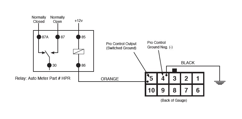
Pro Control
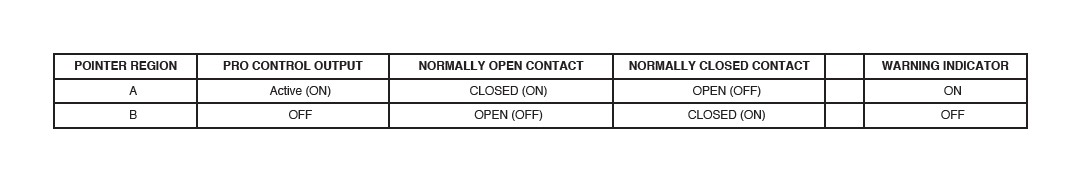
The Pro Control feature activates a switched ground output at a user defined set point. Pro Control can be used to switch on a relay to activate ignition kill, cooling fans, lamps, alarms, etc.
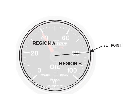
The Pro Control set point is the same as the Warning Indicator set point. Follow the directions above for Warning Indicator to change the set point.
The set point defines two regions on the gauge dial, the region below the set point and the region above the set point. Like the Warning Indicator on the gauge, the Pro Control output is active in the region below the set point (low pressure).
SERVICE
For service send your product to Auto Meter in a well packed shipping carton. Please include a note explaining what the problem is along with your phone number. Please specify when you need the product back. If you need it back immediately mark the outside of the box “RUSH REPAIR,” and Auto Meter will service product within two days after receiving it. ($10.00 charge will be added to the cost of “RUSH REPAIR.”) If you are sending product back for Warranty adjustment, you must include a copy (or original) of your sales receipt from the place of purchase.