 FREE 1 to 3-Day Delivery on Orders $149+ Details
How to Install Addictive Desert Designs HD Off-Road Tie Rod Kit (10-14 Raptor) on your Ford F-150
Tools Required
- Ratchet
- 13/16” Socket
- 3/4” Socket & Wrench
- 15/16” Socket & Wrench
- Crescent Wrench
- 5/8” Ream or Drill Bit
- Side Cutters
- Drill
- Red Loctite
- Zip Ties
PREPARATION
1. Disconnect the negative terminal on the battery. Park the vehicle on level ground and set the emergency brake.
2. Raise your vehicle and support it with jack stands. Never work under an unsupported vehicle.
3. We recommend reading through the installation instructions in whole before performing the work.
4. You will need the following tools:
a. Ratchet
b. 13/16” Socket
c. 3/4” Socket & Wrench
d. 15/16” Socket & Wrench
e. Crescent Wrench
f. 5/8” Ream or Drill Bit
g. Side Cutters
h. Drill
i. Red Loctite
j. Zip Ties
Note: this installation requires 2 people for best results
5. Included in Kit:
2 – Assembled Tie Rods (Inner & Outer)
2 – Clevis
2 – Rack Mount Bolts
2 – Grade 8 Bolts – 1/2-20 x 2 1/4”
2 – Narrow Nylon Lock Nut – 1/2-20
2 – Tie Rod Adapter Posts
2 – Grade 8 Bolts – 5/8-18 x 3 3/4”
4 – Grade 8 Washer – 5/8”
4 – Flex Lock Nut – 5/8-18
2 – Tie Rod Adapter Post Spacers – 1/4” Thick
2 – Tie Rod Rubber Boots
1 – Grade 8 Nut – 5/8-18
REMOVAL
1. The removal process only pertains to vehicles with an OEM Spindle. If you have a fabricated spindle, refer to the manufacturer’s information on how to remove or install your tie rod ends.
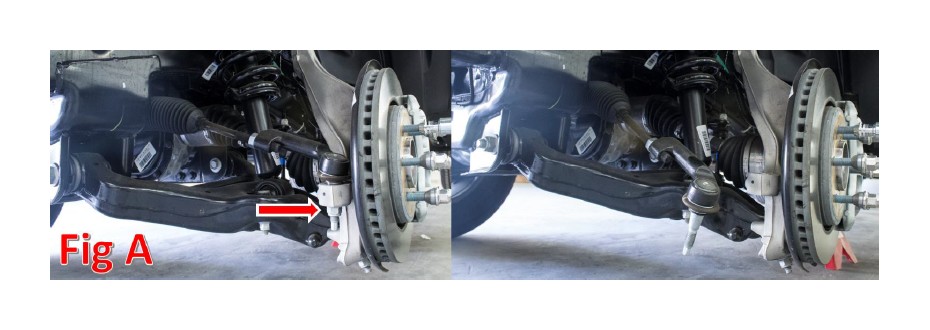
2. Remove the nut holding your OEM outer tie rod in place, then pop the ball joint free from the spindle. (Fig A)
REMOVAL
1. The removal process only pertains to vehicles with an OEM Spindle. If you have a fabricated spindle, refer to the manufacturer’s information on how to remove or install your tie rod ends.
2. Remove the nut holding your OEM outer tie rod in place, then pop the ball joint free from the spindle. (Fig A)
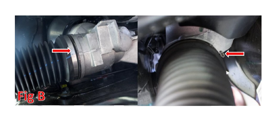
3. Remove the metal band holding the tie rod boot over the inner tie rod/steering rack. Do this by cutting the crimped section of the band. (Fig B)
3. Remove the metal band holding the tie rod boot over the inner tie rod/steering rack. Do this by cutting the crimped section of the band. (Fig B)
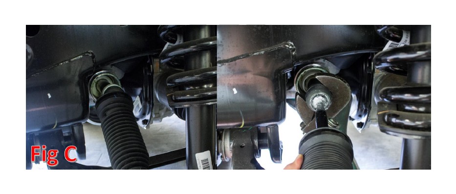
4. Push back the white plastic ring around the outer edge of the inner tie rod end, then use a crescent wrench to spin the inner tie rod off of your steering rack. Once the inner tie rod is removed, slide the plastic ring off of the steering rack shaft. (Fig C)
4. Push back the white plastic ring around the outer edge of the inner tie rod end, then use a crescent wrench to spin the inner tie rod off of your steering rack. Once the inner tie rod is removed, slide the plastic ring off of the steering rack shaft. (Fig C)
5. Repeat Steps 2 & 3 on the opposite side of the vehicle.
5. Repeat Steps 2 & 3 on the opposite side of the vehicle.
INSTALLATION
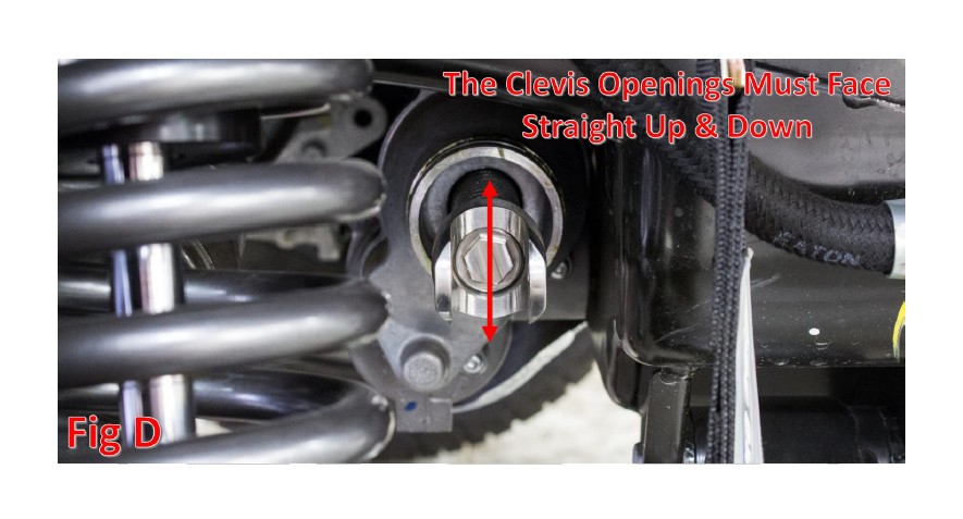
1. Bolt the supplied clevis to your steering rack.
a. Use the supplied Rack Mount Bolt and make sure to apply Red Loctite to the threads before installing.
b. Make sure the clevis is straight up and down as shown in Fig D.
INSTALLATION
1. Bolt the supplied clevis to your steering rack.
a. Use the supplied Rack Mount Bolt and make sure to apply Red Loctite to the threads before installing.
b. Make sure the clevis is straight up and down as shown in Fig D.
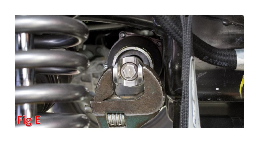
c. We use a crescent wrench to hold the clevis in place, while we use a 3/4” Socket to tighten the Rack Mount Bolt. (Fig E)
c. We use a crescent wrench to hold the clevis in place, while we use a 3/4” Socket to tighten the Rack Mount Bolt. (Fig E)
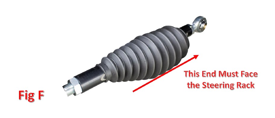
2. Slide the boot onto the tie rod assembly. (Fig F)
a. The two Heim joints on your tie rod assembly are different sizes. There is a 7/8” and 3/4”. The 3/4” Heim joint will be the inner tie rod end that gets bolted to the steering rack.
b. Make sure the large opening of the rubber boot faces the steering rack (3/4” Heim Joint).
c. Slide the boot down and out of the way for now.
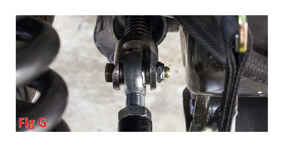
3. Bolt the Inner 3/4” Heim Joint to the clevis that is now secured to your steering rack. Use the supplied 1/2” x 2 1/4” Bolt (x1) and 1/2” Narrow Lock Nut (x1). (Fig G) Be sure to only use the supplied 2 1/4” long 1/2” diameter bolt. Steering rack damage will occur if a longer bolt is used.
3. Bolt the Inner 3/4” Heim Joint to the clevis that is now secured to your steering rack. Use the supplied 1/2” x 2 1/4” Bolt (x1) and 1/2” Narrow Lock Nut (x1). (Fig G) Be sure to only use the supplied 2 1/4” long 1/2” diameter bolt. Steering rack damage will occur if a longer bolt is used.
4. Install the 7/8” Heim Joint to your spindle. The procedure and the hardware used to install this kit on an OEM Spindle versus a Fabricated Spindle is different.
a. If you are using a Fabricated Spindle, follow Step 5.
b. If you are using the OEM Spindle, follow Steps 7-13.
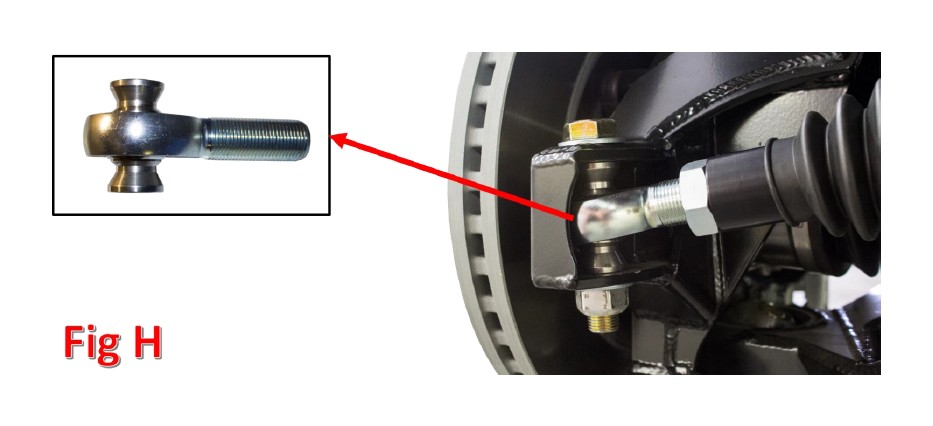
5. FOLLOW THIS STEP IF YOU ARE USING A FABRICATED SPINDLE, OTHERWISE, SKIP TO STEP 7. Since the tie rod comes assembled, you will not need to add any additional spacers or fittings to your spindle side tie rod end. Slide the end into the spindle and secure it using the supplied 5/8” Bolt (x1), 5/8” Washers (x2), and 5/8” Flex Lock Nut (x1). (Fig H)
4. Install the 7/8” Heim Joint to your spindle. The procedure and the hardware used to install this kit on an OEM Spindle versus a Fabricated Spindle is different.
a. If you are using a Fabricated Spindle, follow Step 5.
b. If you are using the OEM Spindle, follow Steps 7-13.
5. FOLLOW THIS STEP IF YOU ARE USING A FABRICATED SPINDLE, OTHERWISE, SKIP TO STEP 7. Since the tie rod comes assembled, you will not need to add any additional spacers or fittings to your spindle side tie rod end. Slide the end into the spindle and secure it using the supplied 5/8” Bolt (x1), 5/8” Washers (x2), and 5/8” Flex Lock Nut (x1). (Fig H)
6. FOLLOW STEPS 7-13 IF YOU ARE USING AN OEM SPINDLE, OTHERWISE, SKIP TO STEP 14.
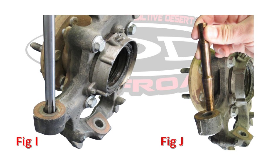
7. Ream out the factory tie rod end location using a 5/8” Ream (a Drill Bit works if there is no Ream available). (Fig I)
8. Place the supplied Spindle Post into the newly reamed tie rod end location. (Fig J)
6. FOLLOW STEPS 7-13 IF YOU ARE USING AN OEM SPINDLE, OTHERWISE, SKIP TO STEP 14.
7. Ream out the factory tie rod end location using a 5/8” Ream (a Drill Bit works if there is no Ream available). (Fig I)
8. Place the supplied Spindle Post into the newly reamed tie rod end location. (Fig J)
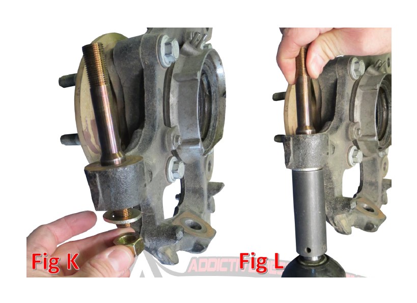
9. Place the supplied 5/8” Washer (x1) and the Gold NON-locking 5/8” Nut (x1) onto the bottom of the ADD Spindle Post. (Fig K)
10. Set the taper by tightening the newly installed 5/8” Non-Locking Nut until the post is fully seated in the spindle. (Fig L)
9. Place the supplied 5/8” Washer (x1) and the Gold NON-locking 5/8” Nut (x1) onto the bottom of the ADD Spindle Post. (Fig K)
10. Set the taper by tightening the newly installed 5/8” Non-Locking Nut until the post is fully seated in the spindle. (Fig L)
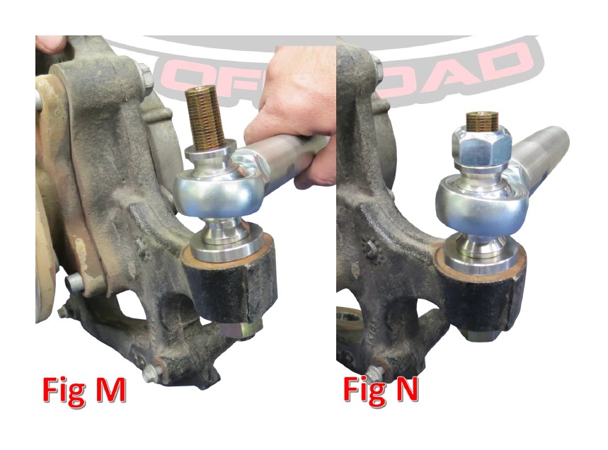
11. Place one of the supplied 1/4” Thick Spacers and the Spindle Side Tie Rod End onto the Spindle Post. (Fig M)
12. Install one of the supplied 5/8” Flex Locking Nuts onto the top of the Spindle Post. Tighten once it is in place. (Fig N)
11. Place one of the supplied 1/4” Thick Spacers and the Spindle Side Tie Rod End onto the Spindle Post. (Fig M)
12. Install one of the supplied 5/8” Flex Locking Nuts onto the top of the Spindle Post. Tighten once it is in place. (Fig N)
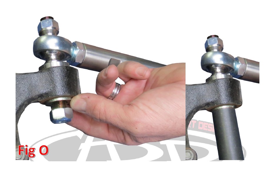
13. Remove the 5/8” Gold Non-Locking Nut from the bottom of the post and replace it with the new 5/8” Flex Locking Nut. Tighten once the Flex Locking Nut is in place. Set aside the Gold Non-Locking Nut for installation on the other side of the vehicle. (Fig O)
13. Remove the 5/8” Gold Non-Locking Nut from the bottom of the post and replace it with the new 5/8” Flex Locking Nut. Tighten once the Flex Locking Nut is in place. Set aside the Gold Non-Locking Nut for installation on the other side of the vehicle. (Fig O)
14. Repeat the entire process on the other side of the truck.
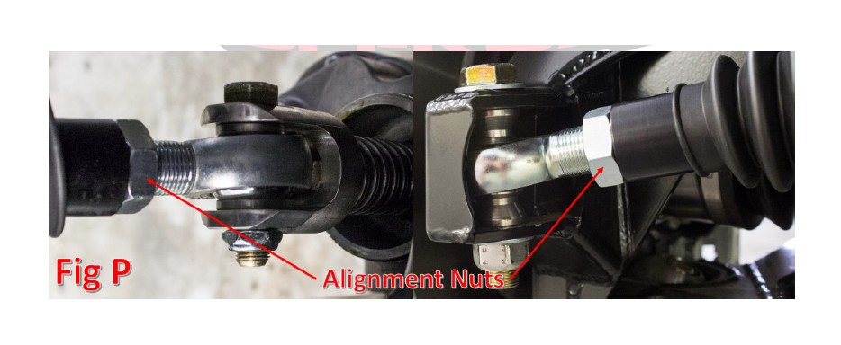
15. ADD recommends doing a rough alignment before tightening your alignment nuts (Heim Jam Nuts). (Fig P)
14. Repeat the entire process on the other side of the truck.
15. ADD recommends doing a rough alignment before tightening your alignment nuts (Heim Jam Nuts). (Fig P)
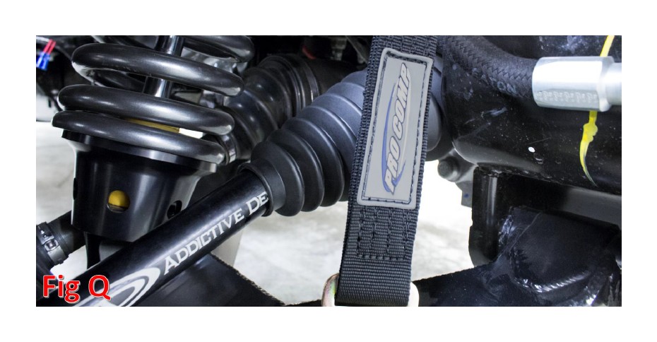
16. After your alignment nuts have been tightened, slide the big end of the rubber boot over the steering rack (covering the Clevis and Heim). Use a zip tie to hold it in place. The small end of the rubber boot doesn’t require a zip tie. (Fig Q)
16. After your alignment nuts have been tightened, slide the big end of the rubber boot over the steering rack (covering the Clevis and Heim). Use a zip tie to hold it in place. The small end of the rubber boot doesn’t require a zip tie. (Fig Q)
17. A front end alignment is required after the installation of this product.
**The alignment shop must be informed that there is a Heim under the boot for aligning purpose. Failure to comply will result in damage or unsafe condition to the clevis and can result in failure of the product entirely**
18. Stand back and enjoy your new ADD Tie Rod Kit.
19. Check and re-tighten if needed, all mounting bolts after 100 miles and periodically thereafter.
