FREE 1 to 3-Day Delivery on Orders $149+ Details
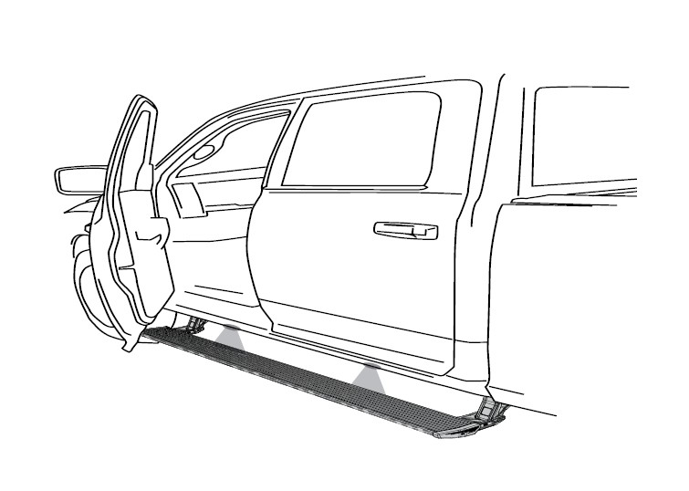
How to Install Amp Research PowerStep Plug-N-Play Conversion Kit on your Ram
Installation Time
1 hours
Tools Required
- Safety goggles
- Measuring tape
- 13mm wrench
- 19mm wrench
- 13mm socket
- 10mm socket
- Ratchet wrench and extension
- Wire stripper / cutter
- 3/16” hex key ( allen wrench )
- 4mm hex key ( allen wrench )
- Rivet Tool
- 1/8”, 9/32” and 3/16” Drill Bit
- T27 torx Bit
- Center Punch
- Anti Corrosion Paint
- Electrical tape

Shop Parts in this Guide
INSTALLATION GUIDEMotor to linkage assembly
CAUTION: HANDLE WITH CARE.
To ensure our customers receive all components with full integrity, we pack the motors separate from their linkage assemblies. This requires that the installer position and fasten the motor before continuing with the install. Please follow the instructions below and handle the assembly carefully.
CAUTION: Dropping the assembly or any excessive impact MAY cause damage to the motor.
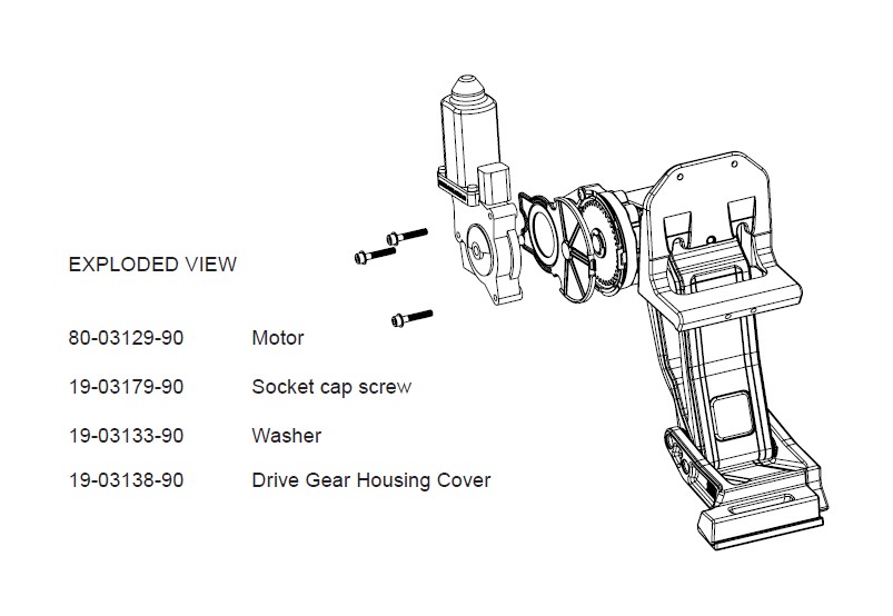
Instructions:
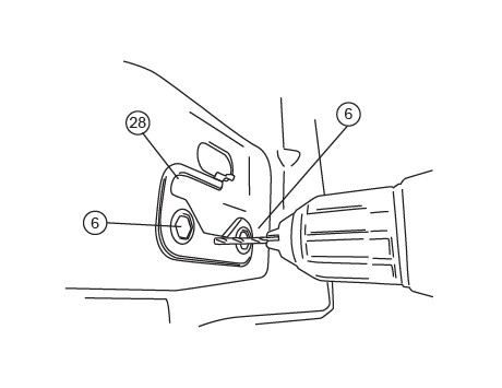
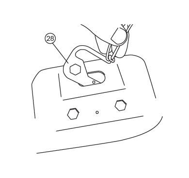
1. Position the gear cover in place as shown if not already in place.
2. Seat motor into position on the three mounting bosses. This may require an adjustment of the gear by moving the swing arms.
3. After seating into place, fasten the motor with the three motor mount screws with 4mm Hex Head. Tighten screws to 36 in-lbs (4N-m). Do not over torque.
NOTE: 1500 RAM Powerstep installations require additional steps and come with the required additional hardware. Please read and carefully follow the instructions in Step 1 for your vehicle model.
Step 1a: ALL1500 MODELS
Follow Steps 2-5 to relocate brake cable and then proceed with the Power Step installation.
Step 1b: ALL 2500/3500 MODELS
Skip to Step 6 and proceed with the Power Step installation. Relocation of the brake cable is not neccessary on Crew Cabs.
Step 2.
While holding brake cable adjustment nut with wrench (located on driverside along frame, towards the rear), loosen brake cable to allow for slack. Mark position of nut before loosening.
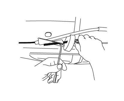
After gaining enough slack, detach brake cable as shown below. This detachment point is located just to the rear of the adjustment nut.
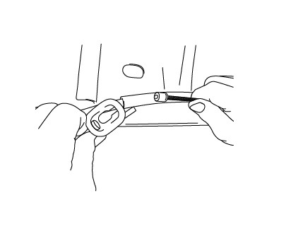
Remove brake cable guide from frame by depressing locking tabs and sliding guide out through hole. Unthread brake cable from frame mount.
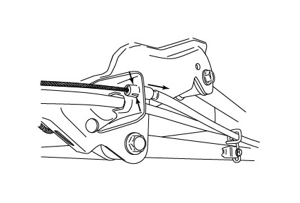
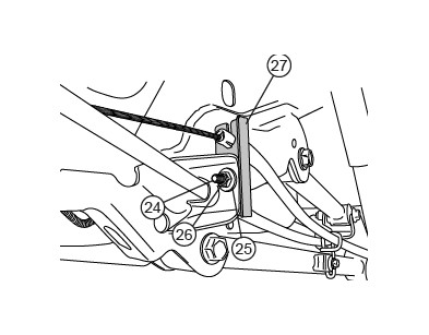
Attach brake cable guide to supplied Brake Cable Bracket (23) and mount bracket with supplied hardware. Reattach brake cable and readjust brake cable adjustment nut to original position.
HARDWARE MOUNTING OVERVIEW
(passenger side shown)
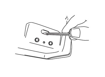
Locate forward most and rearward most mounting provisions on inner sill of truck. Remove tape from sill drain hole at both mounting points.
Set Reinforcement Plate in place and locate with rivet nuts. Drill hole using an 1/8” drill bit. After drilling apply paint to prevent rusting
Once hole is drilled insert a piece of string or wire through hole in Reinforcement Plate. Set plate into position.
Set rivet nuts into place for alignment. Insert pop rivet through hole in plate and secure in place. Once pop rivet is installed remove string or wire from Reinforcement Plate. NOTE: Verify plate is pulled flush to the body before securing pop rivet.
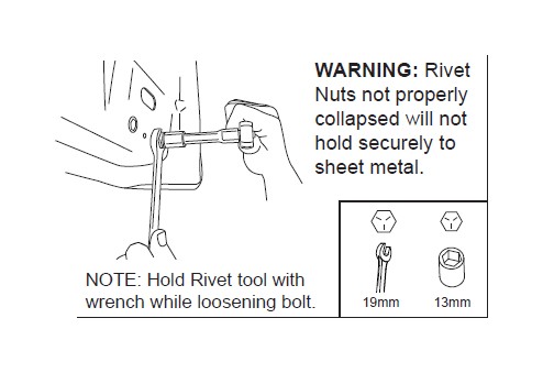
Assemble Hex Bolt (lubricated with soapy water), Washer, Rivet Tool, and Rivet Nut together as shown and place into hex cutouts in sill. An extra Hex Bolt and M8 Washer is supplied to install rivet nuts.
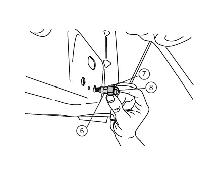
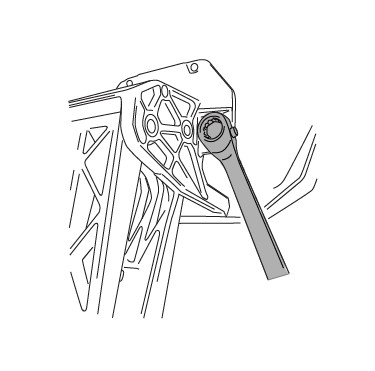
With Rivet Nut Tool held in place with 19mm wrench, tighten Hex Bolt until Rivet Nut deforms and secures itself to the sheet metal (110 in-Lbs. or 4 turns). Remove Hex Bolt and Rivet Nut Tool. Repeat for each of the four mentioned mounting locations.
Once rivet nuts are in place use a screwdriver to push back tab in hole to avoid interference with linkage mount.
NOTE: Models with holes on the pinch weld skip to Step 17. (some 2013 Models)
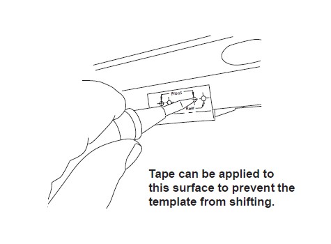
Fold both the passenger and driver side templates in the proper direction noted on the template. Thread in hex bolts and slide slots in template up to bolts. Next use tape and apply tape on all surfaces on template that is labeled “Tape”. Start at Hex bolts and make sure template is flat on each surface. Work your way down and out.
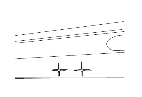
Mark appropriate holes as indicated with a center punch. Front linkage marked “Front” and Rear linkage marked “Rear”.
Using a marker draw cross hatch to verify bit does not walk while drilling.
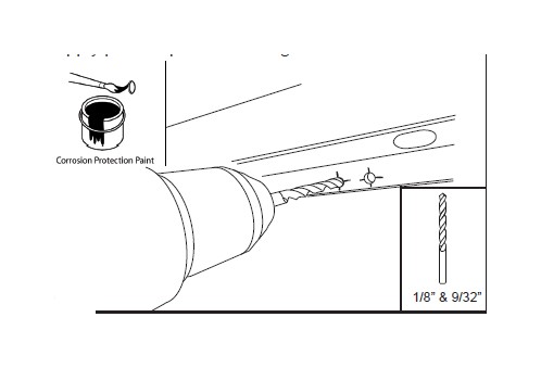
Pre drill hole using an 1/8” drill bit. Next drill holes to 9/32”. Debur all surfaces. NOTE: Filing of hole may be required if drill bit wandered. After drilling apply paint to prevent rusting.
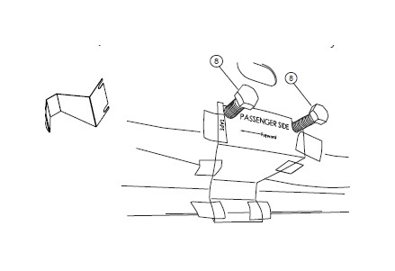
Linkage Installation: On rear linkages thread front hex bolt into rivet nut with washer. Note on Front drive linkages both hex bolts can be threaded into position.
With linkage in position insert Hex bolts into rivet nut locations. Snug bolts but do not tighten. Note: Pre threaded bolt will attach to slot centered on linkage. Idler linkages will use 2 of the 3 mount points.
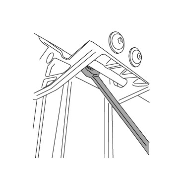
Using a T27 Torx driver start torx bolts and washers. Snug bolts but do not tighten. Note on 2013-current models with pre stamped holes filing may be required if holes do not line up. Do not shift linkage up to align bottom holes.
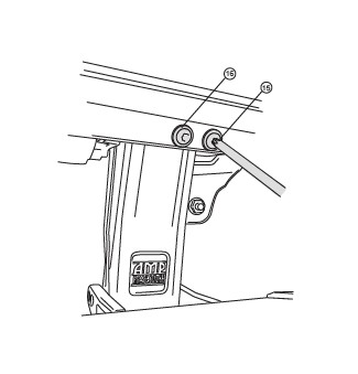
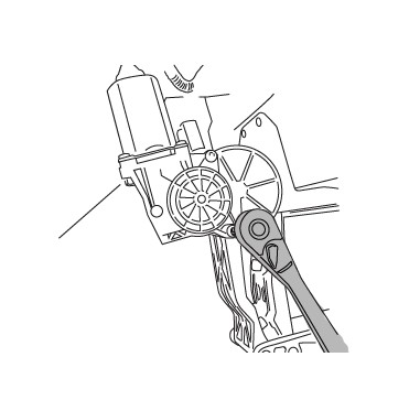
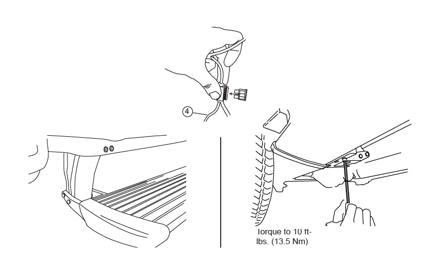
Using a 13mm wrench tighten two hex bolts on linkage. Torque to 16 ft-lbs.
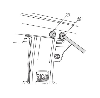
Using a T27 Torx driver torque bolts to 6 ft-lbs.
Using a 4mm hex key torque bolts to 36 in-lbs. See page 2 for motor installation instructions.
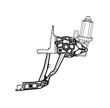
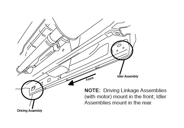
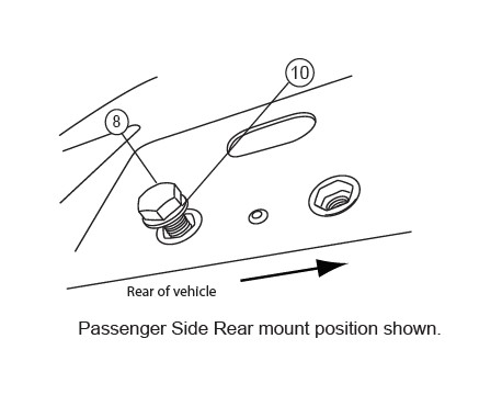
The jogs in the lower part of the linkages point toward one another, as shown, Drive (motor) Linkage in the Front and Idler Linkage in the Rear. Note: Linkage position described in parts list on page 3.
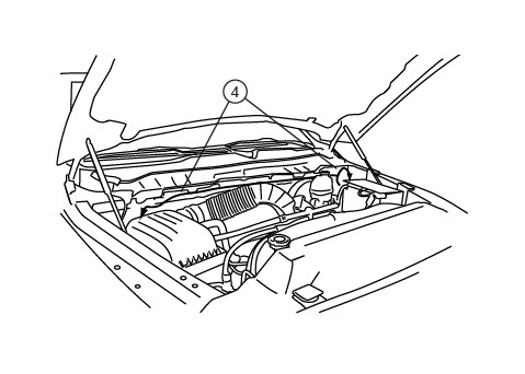
Prepare large tie-wraps for mounting Power Step Controller. Loosely loop tie-wraps around large bundle of wires behind battery in engine compartment.
Insert controller into tie-wrap loops and cinch down securely. The tie-wraps should cinch down into channels on controller surface.
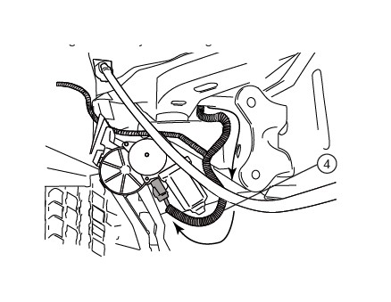
Remove fuse from Power Step Wire Harness.
Connect power leads from Controller, Red to positive battery terminal and Black to the vehicle body ground as shown.
Wiring to Door Ajar Wires: Important notes... Wiring on 2013-2015 vehicles will follow steps 29-35. Wiring on 2009-2012 RAM 1500 and 2010-2012 RAM 2500/3500 vehicles will follow steps 34-39.
Steps 29-33 are for 2013-15 RAM 1500/2500/3500 models.
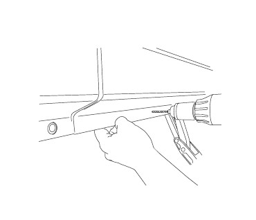
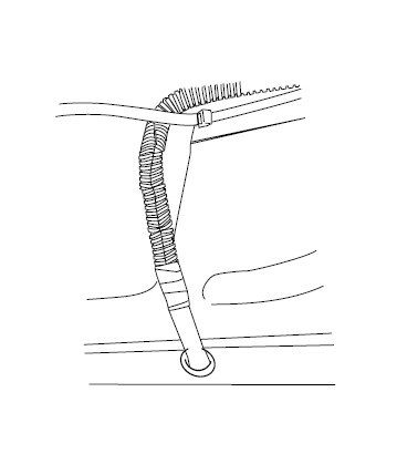
Proceed to STEP 34 for all other models. Locate large rubber wire boot on driver side firewall as shown below. Slice small opening as shown below to run trigger wires through.
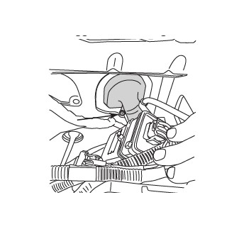
Tape leading end of wires together and push through rubber boot to cabin side of the firewall. Silicon lubricant may be used for ease of passage. The trigger wires will come out just above and to the left of the brake pedal.
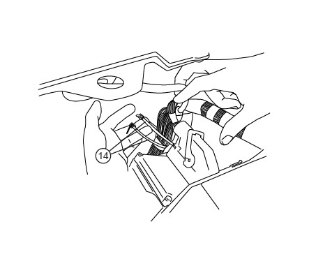
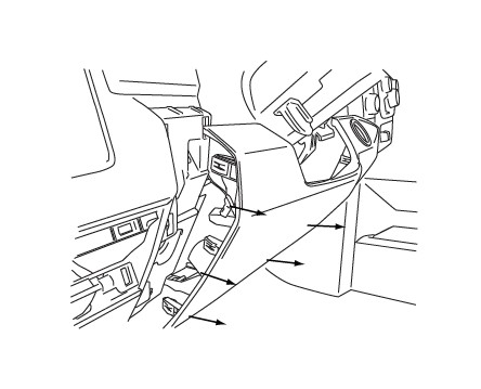
Remove panel below steering column to gain access to trigger wires.
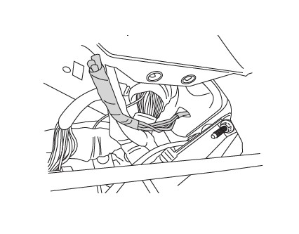
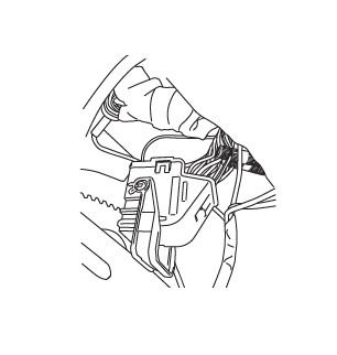
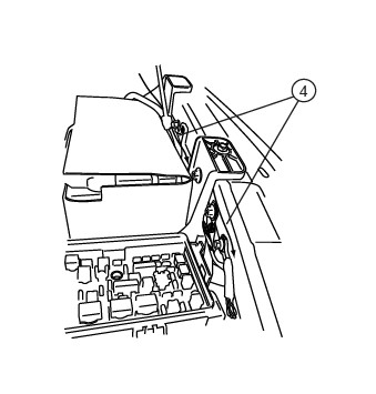
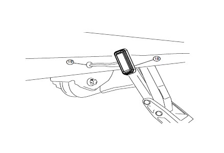
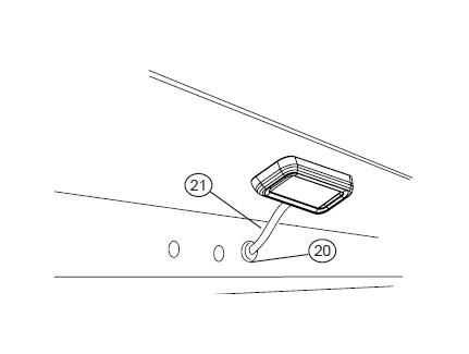
To gain access to white connector panel against driverside firewall panel (inside cab of vehicle), just behind e-brake pedal, some vehicles will have a mounted component that will need to be removed. The component’s bracket can be removed by the three fasteners indicated below.
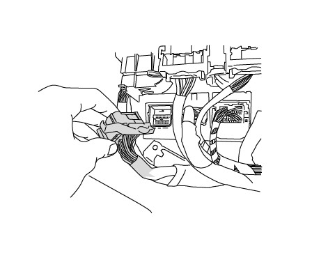
Locate white connector panel against driverside firewall panel, just behind e-brake pedal. Locate three connectors as shown below and connect Powerstep trigger wires as indicated in the chart.
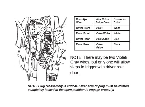
When replacing lever arm plugs ensure lever is in the opened locked position. If lever is not in the fully opened position pins will not engage and components on the vehicle such as (radio, dash and power windows) will not operate.
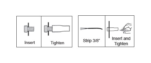
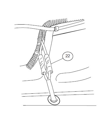
Splice Power Step trigger wires into the Door Ajar wires with provided Posi-TapTM splicers. The Power Step trigger wires color coordinate with the factory Door Ajar wires. Follow the steps below to correctly splice wires.

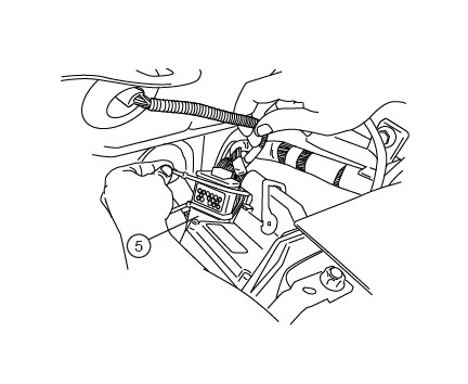
Steps 36-41 are for 2009-2012 RAM 1500 and 2010-2012 RAM 2500/3500.
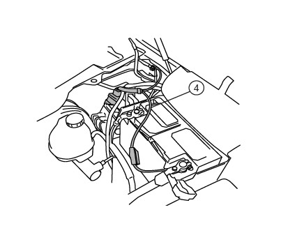
Route the trigger wires of Power Step Harness (Purple wires) down toward the fuse box located in front of the battery.
Remove fuse box lid and fuse box power lead with 13mm wrench. While depressing release tabs, lift fuse box to view bottom side.
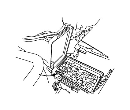
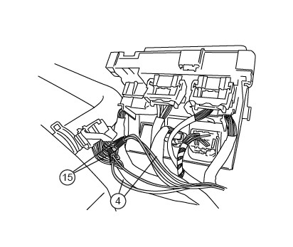
Locate and remove Black Connector with Gray latch on bottom side of fuse box (labeled “G” where connected to fuse box).
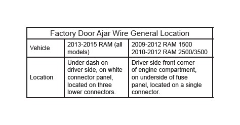
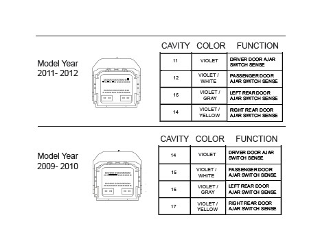
Locate the vehicle’s Door Ajar Switch wires on the removed connector as indicated in chart and diagram below according to vehicle model year.
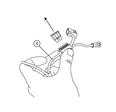
Splice Power Step trigger wires into the Door Ajar wires with provided Posi-TapTM splicers. The Power Step trigger wires color coordinate with the factory Door Ajar wires. Follow the steps below to correctly splice wires.
With Posi-Taps securely in place, carefully replace connector and drop wire bundles and fuse box back into place. Reattach fuse box power lead that was removed in previous step.
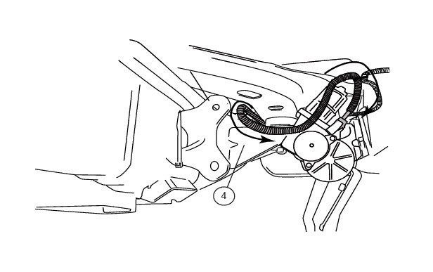
Route the two Wire Harness legs down over the wheel wells toward Motor Linkages, long leg across to the passenger side. Secure harness with tie wraps.
On driver side, run Wire Harness leg down and along underside of the vehicle floor and frame to front Drive Linkage. Connect harness to motor and secure harness with tie wraps. Route remainder of wire harness towards rear linkage assembly for LED lights
On Passenger Side, run Wire Harness leg down and along underside of the vehicle floor and frame to front Drive Linkage. Connect harness to motor and secure harness with tie wraps. Route remainder of wire harness towards rear linkage assembly for LED lights
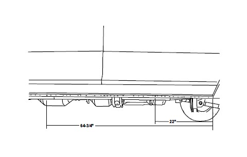
On each side of the vehicle measure from the front edge of door line on the pinch weld to the specified lengths below. Measure at 22” for the front LED Light and 64- 3/4” for the rear LED Light. Note for Quad cabs mount lights at 22” and 54” for Regular cabs mount lights at 10” and 45”.
Drill a 9/32” hole through the pinch weld at marked locations. Debur all holes. After drilling apply paint to holes to prevent rusting
Insert grommet into drilled holes. Insert lamp wires through the grommets. (Silicon lube will help wires slip through grommets.)
Affix lamp to rocker panel surface. Make sure lamp is affixed to a flat, clean surface.
Using supplied butt connectors, connect the lamp wires. Red to Red, Black to Black. Once Crimped use heat gun to shrink tube.
Close and wrap with conduit and electrical tape. Secure all loose wires with cable ties, with lamp wires pulled upward to avoid any wire snagging.
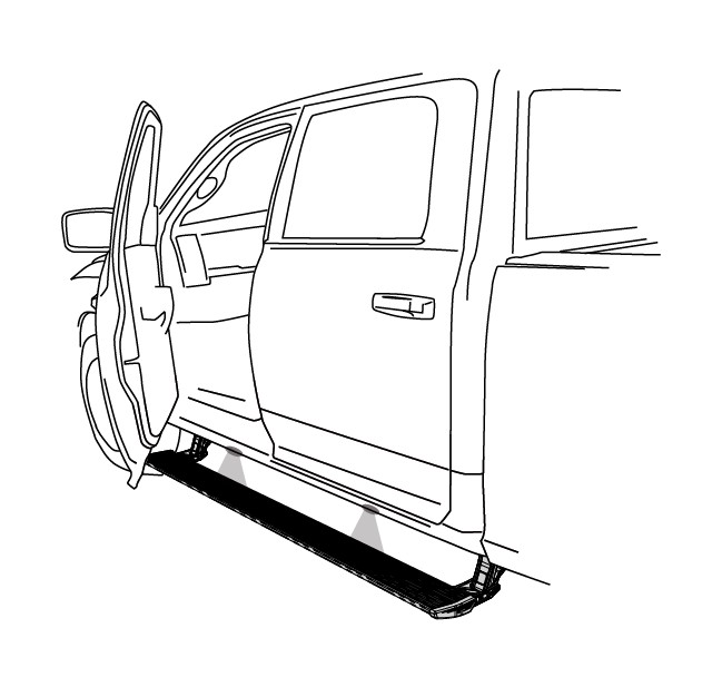
Install boards: Slide mounting T-Nut of board into position and attach to linkages. Shift board forward as much as possible for proper clearance. The end of board/end cap will nest into linkage lower mount 1/2” when positioned correctly. With boards in extended position step on boards to seat linkages. Verify that board end caps do not contact the pinch weld. With both doors open reinstall fuse.
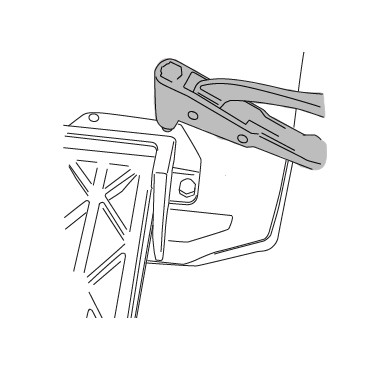
With linkage resting square on the hex bolts Using a 3/16” Drill bit, drill both upper holes in linkage through sheetmetal. After drilling apply paint to holes to prevent rusting.
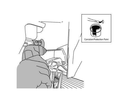
Using a Rivet Gun install rivets.
Check that all doors activate the Power Step and the LED Lights work when doors open and close. Reinstall any remaining trim panels.
FINAL SYSTEM CHECK
Check that all doors activate the PowerStep and the LED lights work when doors open and close.
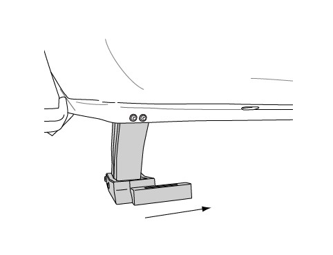
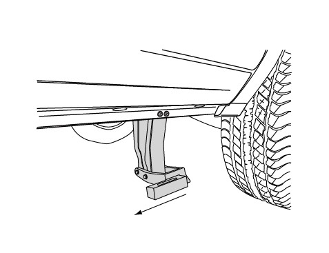
NORMAL OPERATION: When the doors open, PowerStep automatically deploys from under the vehicle. When the doors are closed, PowerStep will automatically return to the stowed/retracted position.
CORRECT OPERATION OF LIGHTS: All four lamps will illuminate upon opening any door of vehicle. Lamps will stay on until restowing of both Power Steps or until 5 minutes has expired with the doors open. When the lights timeout after 5 minutes, they can be reillumintated by closing and opening any door of vehicle.