FREE 1 to 3-Day Delivery on Orders $119+ Details
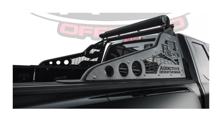
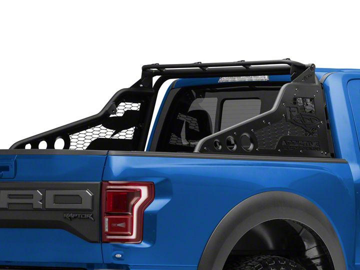
How to Install Addictive Desert Designs Race Series Chase Rack (2017 Raptor) on your Ford F-150
Installation Time
3 hours
Tools Required
- Drill
- 1/2” Drill Bit
- Ratchet
- 3/4” Socket and Wrench
- Sharpie
Shop Parts in this Guide
PREPARATION
1. Disconnect the negative terminal on the battery. Park the vehicle on level ground and set the emergency brake.
2. We recommend reading through the installation instructions in whole before performing the work.
3. Estimated Installation Time: 2.5 Hours
4. You will need the following tools:
a. Drill
b. 1/2” Drill Bit
c. Ratchet
d. 3/4” Socket and Wrench
e. Sharpie
5. Included in Kit:
6 – Hex Head Bolts – 1/2”-13 x 1 1/2”
12 – Flat Washers – 1/2”
6 – Nylon Locking Nuts – 1/2”-13
6 – Mounting Plates
1 – Actuator Toggle Switch
1 – Wiring Harness
INSTALLATION
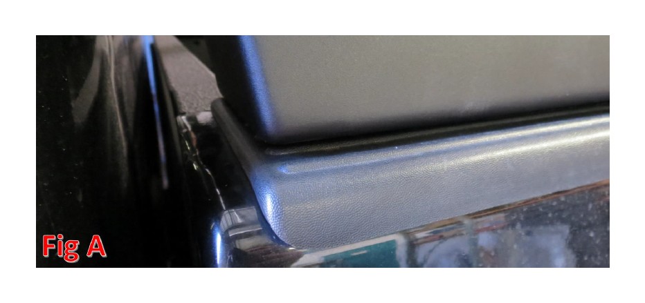
1. Set Race Series R Chase Rack into position on bed cap. Align the front edge of the flat channel to the plastic bed rail cover. (Fig A)
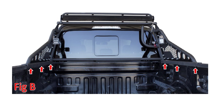
2. Mark the six hole locations with sharpie and move the chase rack out of the way. (Fig B)
3. Drill the 6 marked holes with the 1/2” Drill Bit and Drill.
4. If you purchased any lights for your chase rack, now is a good time to install those.
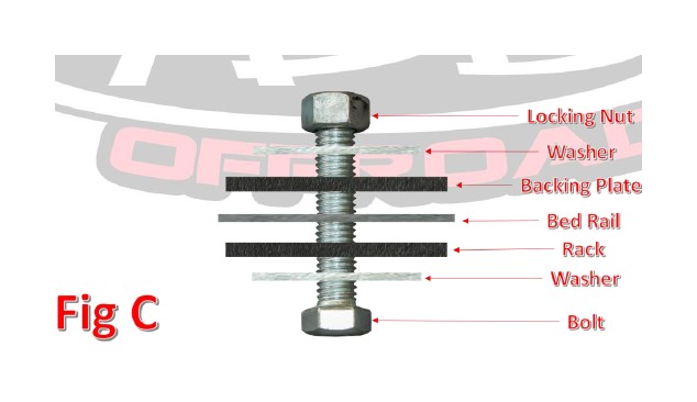
5. Fit the Chase Rack onto the truck and attach it using the supplied 1/2” bolts (x6), 1/2” washers (x12), 1/2” nuts (x6), and mounting plates (x6). Install the bolt with a washer through the chase rack and bed, then add the mounting plate, washer, and locking nut on the backside, in that order. Repeat this for all six bolts. Leave these finger tight until they are all installed, then tighten them to 70 foot pounds. (Fig C)
6. After completing the installation of your Race Series Chase Rack, begin the installation of the wire harness for the actuator by laying out the provided wire harness along the passenger side of the frame rail with the 3 light plugs towards the rear of the truck. Be sure the leave enough room for the plugs to go in between the bed and cab of the truck, up to the bed rail.
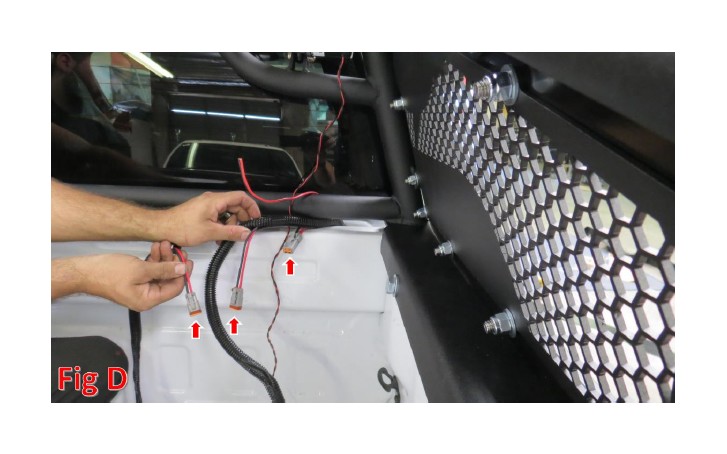
7. Hook all the light plugs to the lights mounted. Secure all the wires. (Fig D)
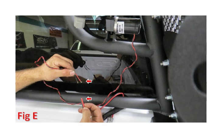
8. Connect the red and black actuator wires on the harness to the red and black wires coming from the actuator. Connect the red to red and the black to black. Secure the wires. (Fig E)
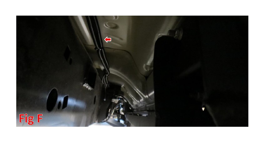
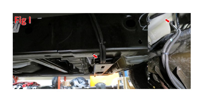
9. Proceed to run the wire harness down the frame rail towards the front of the truck on the passenger side. (Fig F)
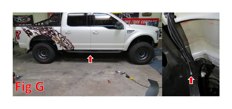
10. Connect the ground (black wire). Pre drill a hole for a self-tapping screw in the body mount at the center of the truck. (Fig G)
11. Here is where the wires will separate and go different directions. The two Red wires with blue butt connectors (for the 50” bar and Duallys) will go forward and into the engine bay on the passenger side.
12. Connect the two Red wires to the Upfitter switches in your truck.
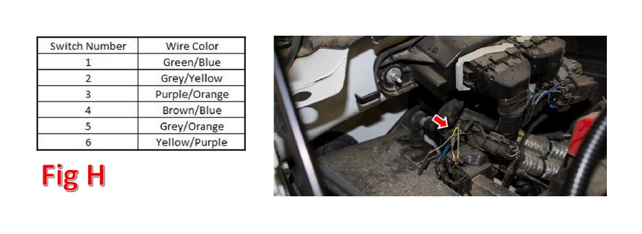
a. Look towards the rear/passenger side of your engine bay. Behind the battery and underneath where the computer sits, there is a bundle of six wires taped to a bigger harness. These are your upfitter switch wires.
b. The larger gauge red wire (for the 50”) needs to be connected to the light bar’s wire harness before it is connected to the Upfitter switch wires. Run the light bar harness as you normally would, but instead of hooking up the supplied switch, connect the relay trigger wire to the Upfitter switch wire that corresponds to the switch number you would like to activate the 50” bar. Then, connect the red power wire that normally gets plugged into the light to the red wire from the chase rack wire harness. You can leave the black wire that normally gets plugged into the light bar disconnected. If you have any questions about which wires in your light bar’s wire harness are the relay trigger or light bar power wires, please contact the light manufacturer as every manufacturer uses different harnesses.
c. Using the butt connector already connected to the end of the remaining red wire (for the Duallys) on your chase rack lighting harness, connect this red wire to the wire for the switch you want the Dually lights to be activated with. Refer to Fig H for wire colors.
13. The other two wires (Red and Black) will cross through the transmission cross member towards the driver’s side of the truck. Then follow up the frame rail to the floor board grommet and bring through floor board. Follow up the dash to desired location for the actuator switch.
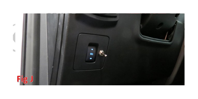
14. Install the switch in desired location (We chose this spot). Use a 7/16” Drill Bit to cut hole in desired switch location. Mount switch in hole with threaded washer.
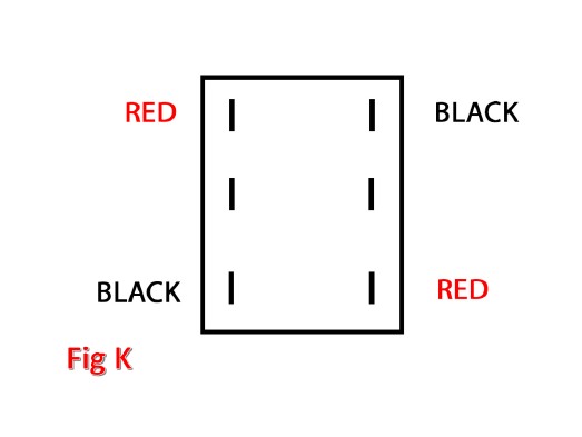
15. On the back side of the switch, connect the both red connections (from your chase rack wire harness) to opposite corners. Then, connect both black connections to the remaining opposite corners. Leave the middle posts unused for now. (Fig K)
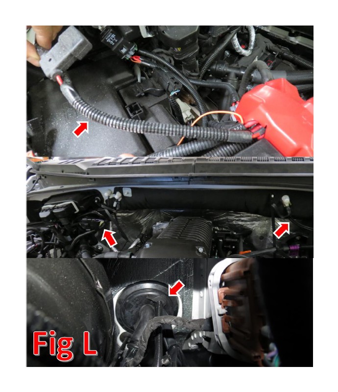
16. Use the second actuator harness for power. Wire this from the battery around the back of the firewall to reach the driver side and pass through the firewall at the rubber grommet. (Fig L)
**We wired ours across the back of the firewall under the stock matting as shown**
17. Bring the wires to the desired location of the switch. Then connect the Red wire to middle post on switch and the Black wire to the opposing post. (Fig M)
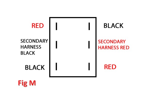
18. Mount the eyelet from the secondary harness to a nearby ground bolt.
19. Test function up and down and make adjustments for switch orientation.
*******Only hold the switch until it stops or light bar is at desired angle for up and down operation. Extended power at max positions may burn out actuator motor********
Be sure to adjust the heim and tighten the nut on the end of the actuator so it does not come out while driving off road with the bar up.
20. Stand back and enjoy your new ADD Race Series Chase Rack.
21. Check and re-tighten if needed, all mounting bolts after 100 miles and periodically thereafter.