FREE 1 to 3-Day Delivery on Orders $119+ Details
Best Sellers


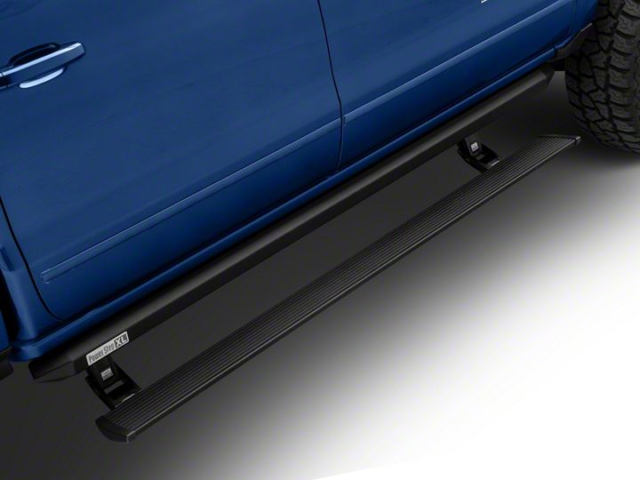
How to Install Amp Research PowerStep XL Running Boards on your Silverado
Installation Time
2 hours
Tools Required
- Safety goggles
- Measuring tape
- Power Drill
- 10 mm socket
- 13 mm socket
- 1/2” socket
- Ratchet wrench and extension
- Wire crimpers
- Wire stripper / cutter
- 3/16” hex key wrench (allen wrench)
- 4mm hex key wrench ( allen wrench )
- Electrical tape
- Weather proof caulking (silicone sealer)
- Silicone spray
Shop Parts in this Guide
INSTALLATION GUIDE
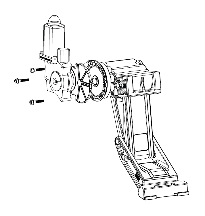
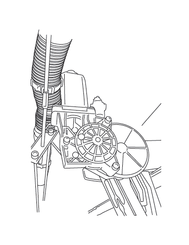
Attaching motor to Linkage assembly.
Exploded View
80-03129-90 Motor
19-03179-90 Socket cap screw
19-03133-90 Washer
19-03138-90 Drive Gear Housing Cover
CAUTION: HANDLE WITH CARE.
To ensure our customers receive all components with full integrity, we pack the motors separate from their linkage assemblies. This requires that the installer position and fasten the motor before continuing with the install. Please follow the instructions below and handle the assembly carefully.
CAUTION: Dropping the assembly or any excessive impact MAY cause damage to the motor.
Instructions:
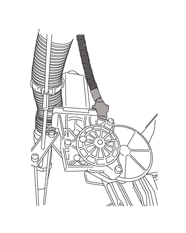
1. Position the gear cover in place as shown if not already in place.
2. Seat motor into position on the three mounting bosses. This may require an adjustment of the gear by moving the swing arms.
3. After seating into place, fasten the motor with the three motor mount screws with 4mm Hex Head. Tighten screws to 36 in-lbs (4N-m). Do not over torque.
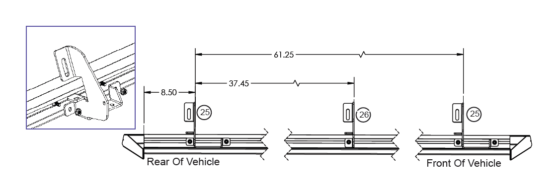
Insert and position Carriage bolts (15) into slot on rail (4). Insert from either end of rail. Using Flange Nuts (12) provided assemble Brackets 2x (25) & 1x (26) onto the rail (4). Driver side shown. Dimensions shown are for reference. Do not tighten this will allow for rail adjustment when mounted onto vehicle.
Note: Badge on rail sits towards the rear of the vehicle!
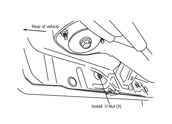
Insert U-Nut in last sheetmetal tab / hole from front.
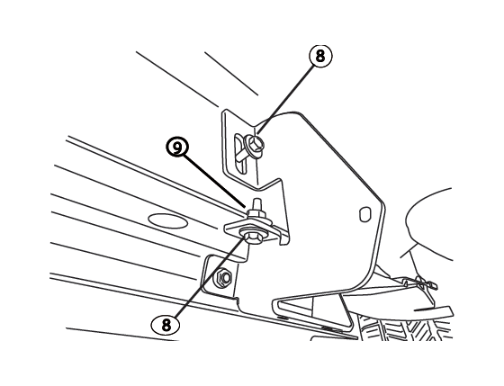
Set rail up into position. Starting with the rear bracket work towards the two front brackets. Attach Bolts 2x (8) and Nut 1x (9). Snug to body do not tighten! Note: Forward and middle bracket may not need nut if threaded insert is present.
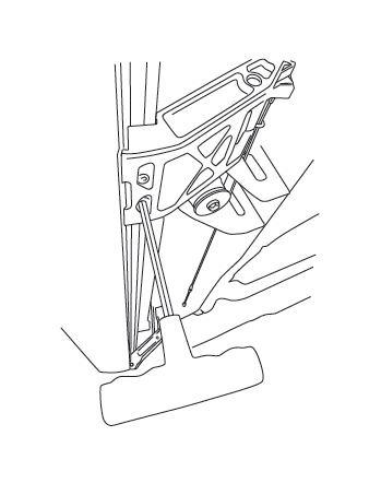
Thread supplied bolts 2x (8) into Rear Drive Linkage. Repeat step for Front Idler Linkage. Do not tighten.
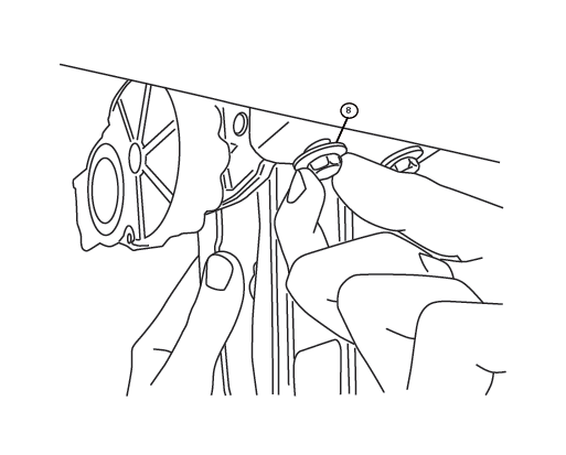
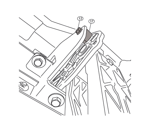
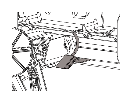
Install provided spacer (17) and M6 bolt (12) into upper mount as shown on both the Drive and Idler linkages. Do not tighten.
Slide mounting T-nut into position, Center board in rail pocket. Tighten fasteners to 10 ft-lbs.
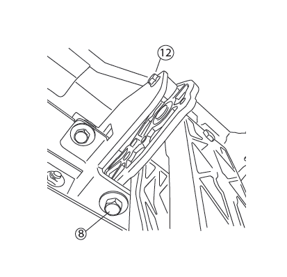
Using a 13mm socket Torque linkage bolts 4x (8) from step 5 to 16 ft-lbs Next use a 10mm socket, torque linkage spacer bolt 2x (12) from step 6 to 8 ft-lbs.
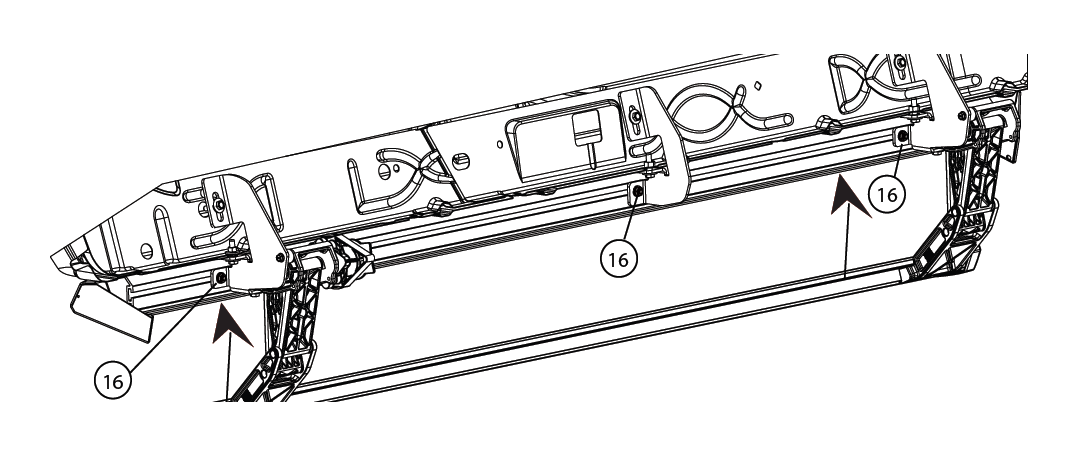
Verify rail clearance at front fender trim and push upwards on rail to ensure rail is snug to the bottom of the linkage mounting bracket. Using a 1/2” socket start at the rear of vehicle and work forward. Torque 5 flange nuts (16) to 16ft-lbs.
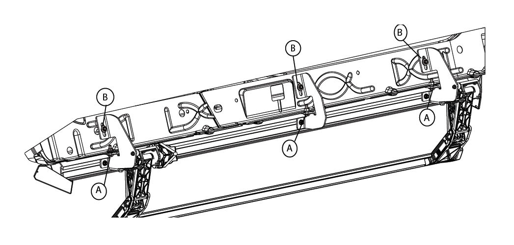
A: Using a 13mm socket tighten 3 bolts along pinch weld first. Torque to 16ft-lbs. B: Next torque 3 upper sill bolts to 16ft-lbs.
Attach motor to harness. Using a 4mm hex Torque to 36 in-Lbs.
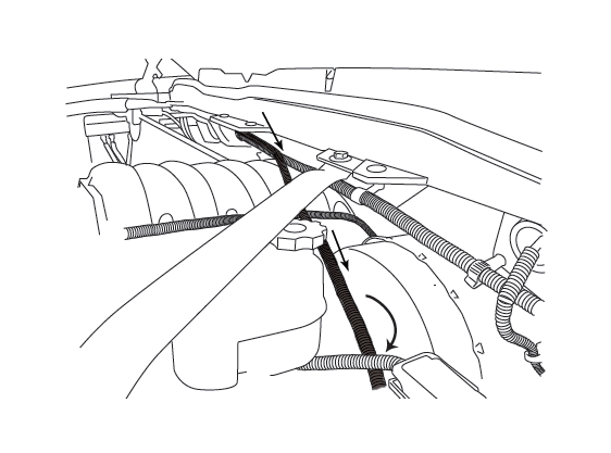
Route long end of wire harness above engine and down through drivers side wheel well. Zip tie harness to cowling clips on fire wall. Route short end down passengers side.
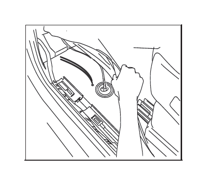
Pull up front door sill plate covers as shown.

Route wire harness along the frame and back towards rear linkages. Secure with zip ties. Push both wires through rubber grommets.
NOTE: Seal holes with silicone glue and cover with tape so carpet does not stick to glue.
Affix LED lamp (21) to LED Bracket (23) as shown.
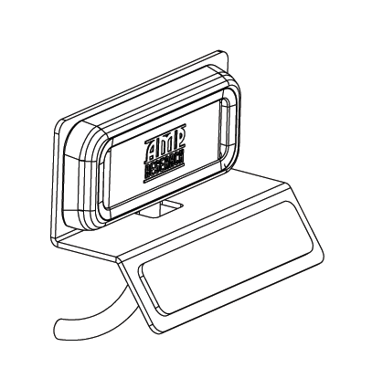
Affix LED light bracket assembly to rail. Mount front light rearward of front linkage and mount rear light just forward of rear linkage.
Using supplied butt connectors, connect the lamp wires. Red to Red, Black to Black. Once Crimped use heat gun to shrink tube. Close and wrap conduit with electrical tape. Secure all loose wires with cable ties. Pull lamp wires upward to avoid any wire snagging.

Connect harness to motor. Secure harness with tie wraps.
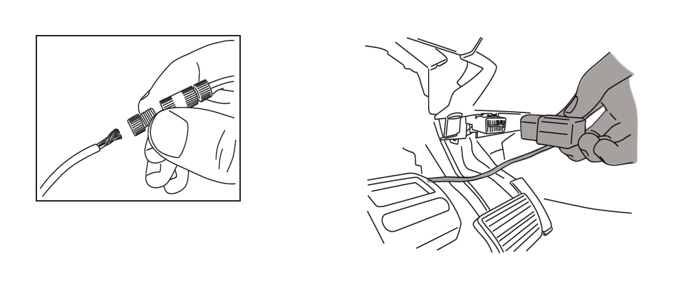
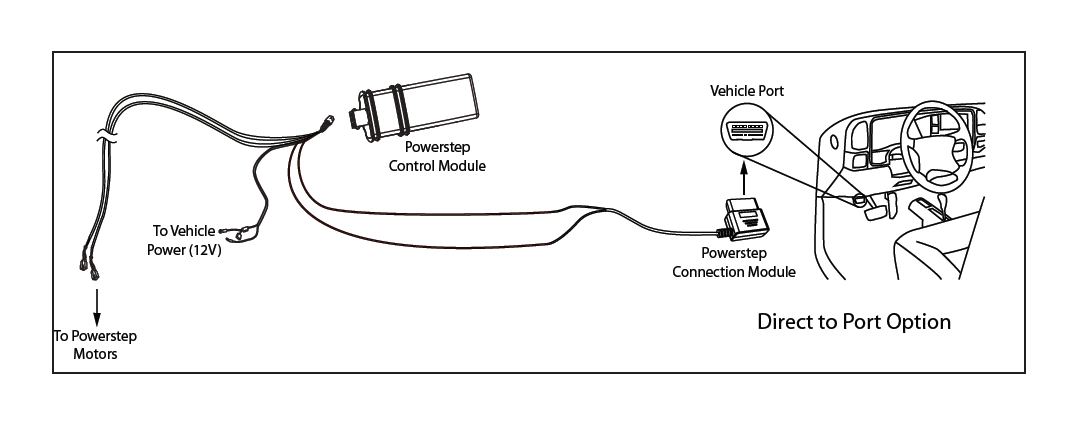
OBD II install: Use Supplied Posi Twist connectors to attach the Plug and Play Module to the Harness. Attach matching colors on the harness to the wires on the module. Plug in module to OBD II port on the vehicle. Secure harness with supplied tie wraps.
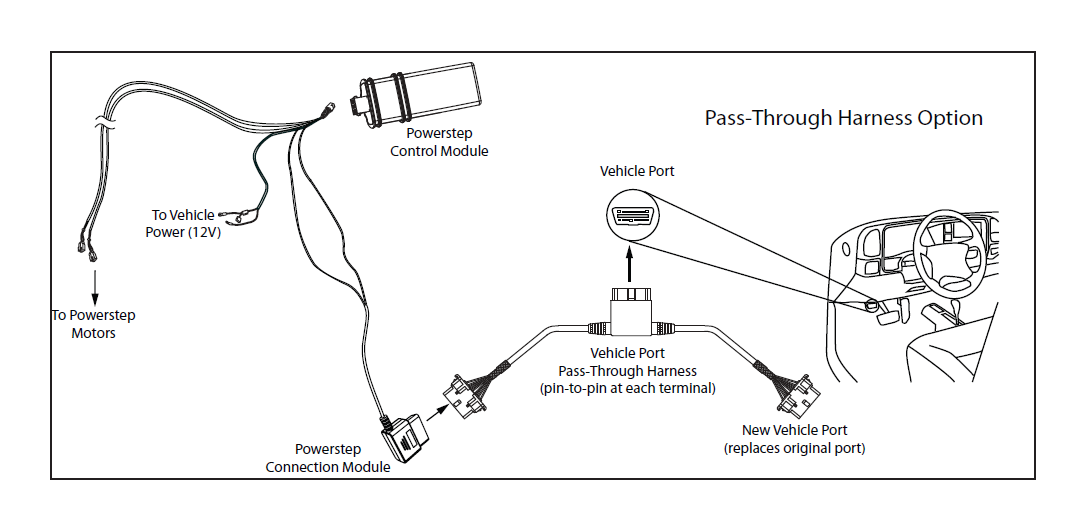
Note: If the OBD II pass thru harness (76404-01A) was purchased see install sheet supplied in packaging. The pass through harness allows for an open port for other accessories. See next page for a brief description.
Check that all doors activate the Power Step and the LED Lights work when doors open and close. Reinstall any remaining trim panels.
FINAL SYSTEM CHECK
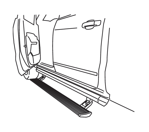
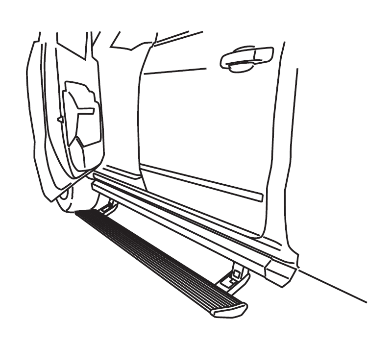
Check that all doors activate the PowerStep and the LED lights work when doors open and close. NORMAL OPERATION: When the doors open, PowerStep automatically deploys from under the vehicle. When the doors are closed, PowerStep will automatically return to the stowed/retracted position. Note that there is a 2-second delay before the PowerStep returns to the stowed/retracted position.
CORRECT OPERATION OF LIGHTS: All four lamps will illuminate upon opening any door of vehicle. Lamps will stay on until restowing of both Power Steps or until 5 minutes has expired with the doors open. When the lights timeout after 5 minutes, they can be reillumintated by closing and opening any door of vehicle.